
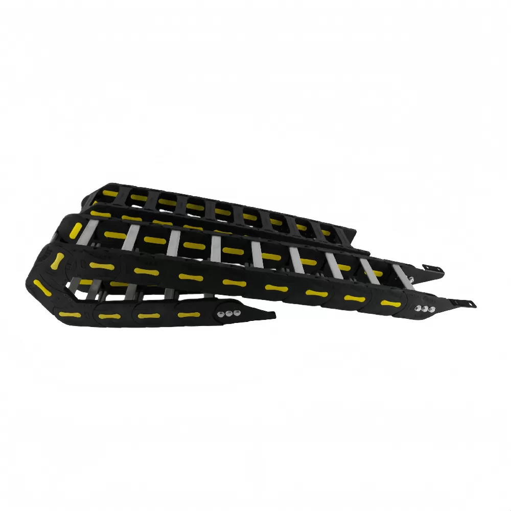
Dynamic cable management stands as one of the most critical yet frequently underestimated disciplines in industrial automation, high-speed CNC machinery, and robotics. As manufacturing systems trend toward higher linear velocities, aggressive acceleration curves, and multi-axis kinematic complexity, the dynamic conduits housing power lines, signal feedback, and fluid hoses undergo severe mechanical stress. A properly designed cable chain track acts as an engineered protective skeleton, absorbing mechanical loads, dictating allowable bend radii, and isolating internal conductors from frictional wear, torsional fatigue, and hostile manufacturing atmospheres.
Premature degradation of internal wiring and pneumatic lines leads to unplanned production downtime, signal degradation, and catastrophic failure of sensitive servomotors. Modern machine architects must move past rudimentary sizing charts and treat dynamic guide carriers as precision components governed by mechanics, tribology, and kinematics.
Mechanics of Dynamic Stress: Cable Wear and Torsional Fatigue in Automated
Tooling
Every reciprocating motion in an automated axis induces physical forces across every layer of an internal conduit. When a moving axis accelerates, inertia pushes internal media against the boundary walls of the enclosure. Without engineered management, three structural failure mechanisms dominate dynamic cable runs:
Tensile Over-extension: Repetitive linear strokes pull outer cable jackets past their elastic deformation limit, particularly when bend radii contract beyond the cable manufacturer's specification.
Torsional Imbalance (The Corkscrew Effect): Multi-conductor cables twisted during installation build internal shear strain. During cyclic bending, this energy releases unevenly, forcing core conductors to burst radially through the jacket wall.
Abrasive Friction and Shearing: Cables and hydraulic lines laid together without internal segregation grind against one another under rapid acceleration, wearing jackets down to shielding braids and fluid layers.
Mitigating these issues requires an analytical approach to the carrier's internal cross-section. Interior cavity dividers must decouple dissimilar lines, establishing independent channels so heavy hydraulic lines do not exert transverse pressure onto sensitive fiber-optic or high-frequency encoder wiring.
Material Sciences in Cable Chain Track Engineering
Operational conditions dictate whether an installation demands an engineered polymer carrier, an all-metal assembly, or an intermediate hybrid structure. The structural profile of a cable chain track must maintain dimensional stability across millions of cycles while tolerating chemical mist, chips, and extreme temperatures.
Engineering-grade polyamides, specifically glass-fiber-reinforced PA66, represent the primary material for dynamic automation systems running at speeds exceeding 5 m/s. The reinforcement matrix elevates tensile modulus, lowers creep rates under prolonged mechanical loads, and preserves pin-joint integrity. PA66 compounds possess natural damping properties, directly lowering decibel emissions in linear motion platforms. In cleanroom and electronics assembly spaces, advanced polymer formulations prevent particulate shedding caused by joint friction, achieving ISO Class 1 compliance.
Heavy metallurgical processing, open-bed metal cutting, and foundries expose guidance assemblies to continuous red-hot swarf, slag, and sustained radiative heat. In these operating regimes, zinc-plated steel or AISI 304/316 stainless steel builds provide structural defense. Steel configurations tolerate hot chip impact without surface melting, though higher mass limits travel velocity and introduces substantial system inertia that machine drives must compensate for. High-standard manufacturing protocols, such as those maintained by QUNHUI, verify that polymer link pins and steel link plates achieve precise surface clearances, minimizing mechanical play and mitigating dynamic hinge wear over extended operational horizons.
Sizing Methodology and Kinematic Parameter Calculations
Sizing dynamic carriers requires calculating specific kinematic values rather than relying on geometric estimates. Machine builders must evaluate unsupported length, dynamic fill ratios, and permissible bend radii to guarantee reliable axis operation.
Unsupported Length Dynamics
The unsupported length ($L_U$) defines the span over which the upper run travels above the lower run without physical contact or sag beyond allowable deflection thresholds. Two distinct operating conditions govern this metric:
Unsupported with Straight Upper Run ($F_L$): The track stays fully horizontal without measurable deflection, representing the baseline for high-acceleration machinery.
Unsupported with Permissible Sag ($F_B$): The carrier exhibits controlled sag without scraping against the lower run or frame obstacles. This operating state allows longer travel distances before switching to gliding assemblies, though it limits maximum axis velocity and acceleration.
When stroke length exceeds the unsupported threshold, the assembly shifts to a gliding arrangement. In gliding operations, the upper run drops down to slide directly atop the lower run within high-walled guide channels, necessitating materials with low dry-sliding coefficients of friction to prevent thermal buildup and chattering.
Bend Radius ($R$) Determination
Bend radius directly controls the flexural cycle life of dynamic lines. Sizing the carrier radius requires isolating the single thickest or stiffest cable or hose within the prospective bundle. As an engineering baseline:
Standard dynamic electrical cables dictate a minimum bend radius between $7.5 \times d$ and $10 \times d$ (where $d$ is the outer cable diameter).
Pneumatic polyurethane tubing demands a minimum radius between $8 \times d$ and $10 \times d$.
Hydraulic high-pressure hoses require an expanded radius between $12 \times d$ and $15 \times d$ to prevent wall collapse and inner-tube delamination under pressure pulses.
Selecting a carrier bend radius larger than the maximum calculated cable requirement significantly lowers core fatigue, extending dynamic cycle life across continuous production schedules.
Calculating Total Carrier Length
For horizontal strokes where the fixed end resides at the exact center of travel, calculate overall track length using the following engineering formula:
$L = \frac{S}{2} + K$
Here, $L$ equals the total developed length of the carrier, $S$ corresponds to the full stroke length of the moving axis, and $K$ represents a constant derived from the bend radius ($K = \pi \times R + (2 \times P)$, where $P$ is the link pitch). Offsetting the fixed bracket away from the geometric midpoint scales the required length proportionally to the displaced axis coordinates.
Internal Space Allocation and Weight Distribution
Cavity overfill causes extensive damage in continuous-flex systems. Dynamic cables require unimpeded freedom of motion as they cycle through the neutral axis of bending. Cramming lines into an enclosed pocket produces lateral pinning forces, rapid sheath thinning, and localized heating.
Designers must implement a structural clearance margin. The aggregate cross-sectional area of internal cables and hoses must not exceed 60% to 70% of the usable inner carrier cross-section. Every cable must have at least 10% of its outer diameter (minimum 1.5 to 2 mm) as clearance between adjacent separators and vertical side links.
Uneven weight distribution across the horizontal axis of the carrier induces lateral tracking runout. Heavier components, like multi-conductor motor cables and reinforced hydraulic runs, must sit symmetrically along outer edges or evenly balanced around the central vertical axis. Lighter signal, sensor, and optical media belong within the center channels. Vertical cross-separators should isolate lines of substantially different diameters to prevent thinner lines from slipping under adjacent cables, which can wedge the track during high-speed direction reversals.
Harsh Environment Deployment: Particulate, Swarf, and Thermal Deflection
Operating environments introduce external hazards that dictate dynamic carrier architecture. Selecting between an open-frame crossbar style and an enclosed-tube cable chain track configuration hinges on environmental contaminant profiles.
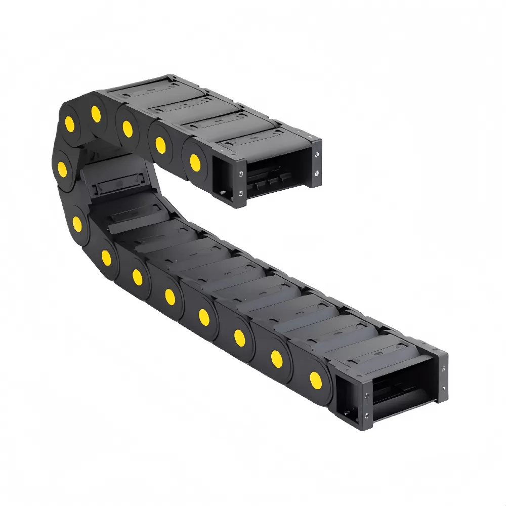
Open-frame carriers allow fast visual inspection, lower moving mass, and let debris fall through without accumulating within the link hinges. These units excel in clean automation, assembly robotics, pick-and-place systems, and secondary packaging equipment. Conversely, multi-axis milling, turning, and aerospace composite machining centers generate high volumes of sharp aluminum chips, fine cast-iron dust, hot steel swarf, and pressurized flood coolant. In these environments, open designs invite debris ingress; chips settle between link segments, physically locking pin joints and damaging cable jackets.
Enclosed-tube configurations utilize overlapping polymer or steel cover plates to deflect pressurized coolants, aggressive lubricants, and abrasive particulate matter away from internal lines. Precision tongue-and-groove joint profiles prevent flying metal chips from infiltrating the interior cavity while still allowing full articulated bending along the primary axis. In high-performance tooling systems developed by custom machine specialists such as QUNHUI, fully enclosed, chip-resistant carriers maintain axis reliability across continuous multi-axis milling cycles where coolant pressure exceeds 20 bar.
Integration Protocols for Multi-Axis CNC Machining Centers
Advanced subtractive platforms present complex mechanical kinematics that break standard single-axis routing rules. Tool-changing gantries, moving-column structures, and 5-axis articulation demand distinct carrier strategies.
Long-Travel Gliding Troughs
When axis strokes extend beyond 6 to 10 meters, such as in heavy gantry mills and waterjet cutting tables, carrier runs must sit within dedicated guide troughs. Aluminum or stainless steel trough walls prevent lateral buckling and hold the gliding upper run parallel to the lower run. Proper trough installation demands exact track alignment, low-friction side glide shoes, and an integrated reverse-bend radius entry ramp to guide the floating end down smoothly without mechanical shock.
Multi-Axis and Spherical Articulation
Articulated robotic wrists and tilting CNC spindle heads demand three-dimensional mobility. Standard single-axis pin links cannot absorb multi-planar twisting. Imposing torsional moments across a standard single-plane chain will shear hinge pins and snap polymer crossbars. Multi-axis 3D dynamic carriers employ ball-and-socket link interfaces, providing controlled omnidirectional mobility that accommodates compound rotation and twisting while maintaining a defined minimum bend radius along every active vector.
Strain Relief and Anchoring Protocols
Effective dynamic cable management depends entirely on proper terminal strain relief. Internal conductors must never absorb external tensile loads. Anchor every line securely at both the moving bracket and the fixed base bracket using specialized strain relief comb plates, pneumatic clamp blocks, or C-rail clamps fitted with elastomer saddles.
Fasten cables strictly along their neutral axis without over-torquing clamps to the point of jacket deformation. Technicians must leave adequate slack within the carrier cavity; cables must not be pulled tight against the internal radius curve, nor pushed outward against the external links. Proper alignment allows cables to move freely during dynamic operation without dragging across link dividers.
Systematic Failure Modes and Predictive Diagnostics
Analyzing field failures reveals distinct mechanical patterns that dictate corrective maintenance actions:
Jacket Abrasion and Material Migration: Indicates a missing or broken internal vertical separator, causing differing jacket chemistries (e.g., PVC against PUR) to abrade each other via dry contact friction.
Link Hinge Pin Breakage: Points to excessive axial acceleration that exceeds the shear rating of the pin polymer, severe lateral deflection caused by misalignment, or debris packing the hinge cavity.
Wavy Track Motion (Snake Trajectory): Occurs when the carrier operates past its unsupported limit without a guide trough, or when broken joint stops permit irregular reverse flexing.
Internal Cable Corkscrewing: Stems from clamping twisted cables into strain relief blocks without letting them untwist via gravity before installation, or ignoring dynamic clearance margins within the carrier.
Modern smart manufacturing facilities increasingly incorporate condition monitoring directly into dynamic guide chains. Embedded diagnostic modules monitor link temperature, pin joint clearance, tension force on tow brackets, and acoustic profiles during operation. Changes in system pull-force signal debris accumulation within the guide trough or imminent bearing seizure, allowing scheduled maintenance before unexpected operational shutdowns.
Specifying a Custom Cable Chain Track for Dynamic Automation
Standard catalog components do not always meet the demands of advanced custom machinery. Complex multi-axis configurations, extreme strokes, and aggressive acceleration profiles demand dedicated engineering calculations to select the ideal cable chain track configuration. Engineering teams evaluate dynamic operating profiles alongside environmental hazards to configure an assembly that balances durability, mass, and volumetric efficiency.
Specifying a carrier assembly requires reviewing dynamic operational parameters:
Total dynamic payload mass (kg/m) including all conductors, hoses, and contained fluid volumes.
Operating travel distance, velocity, acceleration, and deceleration profiles across all dynamic axes.
Ambient temperature ranges, airborne abrasive concentrations, and exposure to corrosive cutting fluids or chemical agents.
Permissible geometric footprint within the machine envelope, accounting for dynamic carrier curve heights and safety clearances.
Frequently Asked Questions (Technical Reference)
What is the primary difference between open crossbar and fully enclosed carrier designs?
Open crossbar carriers provide fast visual inspection, minimal total weight, and clear pathways for debris to fall through. They are ideal for clean automation, packaging, and electronics manufacturing. Enclosed designs use overlapping hinged covers to protect internal lines from hot metal chips, abrasive swarf, cutting fluids, and dirt common in CNC milling, turning, and heavy industrial machining.
How do I prevent the corkscrew effect in dynamic multi-conductor cables?
Preventing the corkscrew effect requires unrolling cables directly from their shipping spools rather than looping them off the reel flange, which introduces structural twists. Allow cables to hang freely before installation to release residual mechanical strain. Inside the carrier cavity, isolate cables using vertical dividers, ensure at least 10% diameter clearance around each line, and clamp them firmly at both ends with dedicated strain-relief combs.
When must a dynamic carrier switch from unsupported travel to a gliding configuration?
The transition depends on total fill weight per meter and travel distance. Polymer carriers typically support horizontal travels up to 4 to 6 meters unsupported before upper run sag exceeds allowable limits. Once the stroke length passes this threshold, the assembly must run in a continuous gliding trough to prevent structural deflection, link damage, and erratic motion.
Can hydraulic lines, pneumatic lines, and electrical cables share the same carrier?
Yes, provided the interior cavity is mechanically partitioned. Heavy hydraulic hoses must be separated from electrical lines using sturdy vertical dividers to prevent abrasive wear and physical crushing. High-pressure hydraulic lines pulse under load, meaning they must sit in dedicated compartments with sufficient clearance to expand without impacting adjacent signal or bus lines.
How is the minimum allowable bend radius determined for an entire carrier bundle?
The carrier's bend radius must match or exceed the highest minimum bend radius among all enclosed lines. Evaluate the outer diameter of the thickest cable or hose, apply the manufacturer's dynamic bending factor (typically 7.5x to 10x for dynamic cables; 12x to 15x for hydraulic lines), and choose a standard carrier bend radius that clears this benchmark to prevent dynamic fatigue.
Engineering Consultation and Application Support
Specifying high-performance motion management for complex automation, heavy-duty CNC systems, or dynamic multi-axis machinery requires precise engineering. The technical engineering team at QUNHUI develops industrial-grade dynamic cable guidance systems tailored to custom kinematic profiles, intense cycle duty, and severe workshop environments. Submit your axis travel drawings, operational velocity profiles, payload specifications, and spatial boundaries to our engineering department for comprehensive design validation, kinematic load calculations, and custom production estimates.