

Modern automated machinery relies entirely on flexible conduit systems to route power, data, and pneumatic media. When an automated gantry or CNC axis moves, the internal conduits endure millions of continuous cycles. Selecting an undersized or poorly configured drag chain cable tray leads straight to jacket abrasion, severed conductors, and unexpected factory shutdowns.
At QUNHUI, we inspect hundreds of industrial automation installations every year. The root cause of premature line failure rarely stems from the cable quality itself. Instead, mechanical binding, improper clearances, and incorrect bend radii inside the dynamic carrier cause early line destruction. Dynamic carriers demand a completely different mathematical approach than stationary wireways.
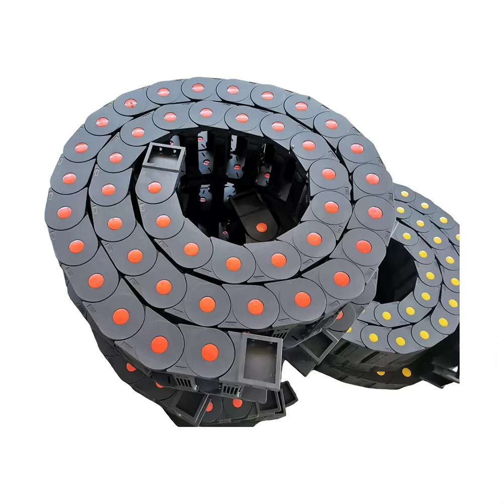
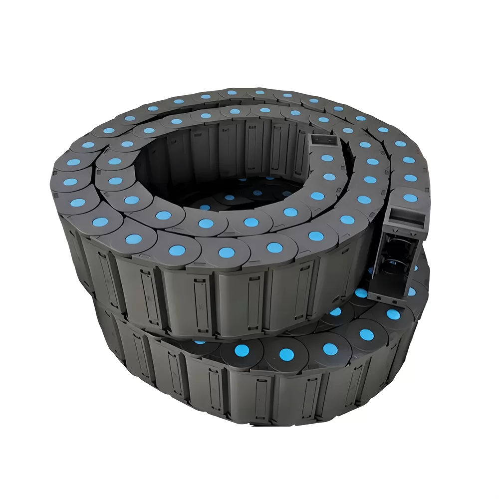
Stationary cable trays hold static dead weight under gravity. A dynamic drag chain cable tray—also called an energy chain or dynamic cable carrier—operates as a moving machine element. It must withstand tensile loads, lateral acceleration, continuous flexing, and abrasive wear. This engineering guide covers the step-by-step calculations required to size dynamic carriers correctly the first time.
Step 1: Cable and Hose Data Audit
Every reliable dynamic calculation starts with a physical audit of the media passing through the carrier. Never estimate or use nominal sizes from generic catalogs. Minor production variations between cable brands alter outer diameters enough to jam an entire assembly.
Gather the exact technical specification sheets for every element. You must record three critical values for each conductor, air tube, and hydraulic hose:
Outer Diameter (OD): Measure actual samples with a digital caliper whenever possible, noting the widest point on oval cables.
Weight per Meter (kg/m): Essential for calculating total chain fill weight, push/pull loads, and unsupported spans.
Dynamic Bend Radius: This differs significantly from static installation values. Most dynamic industrial cables require minimum radii between $8\times\text{OD}$ and $12\times\text{OD}$.
You must also enforce cable grouping disciplines. Power cables generate electromagnetic interference (EMI) and run hot. Data lines and fiber optics are fragile and sensitive to noise. Pneumatic hoses expand and contract radially under pressure cycles.
Never pack pneumatic tubes tightly alongside heavy servo cables without physical dividers. Hydraulic hoses alter their physical length under high pressure. They require dedicated compartments to slide freely without pinching adjacent sensor lines.
Step 2: Core Engineering Formulas & Sizing Parameters
Carrier manufacturers use standardized parameters to define cavity dimensions. Applying deliberate safety margins to your measurements protects the bundle from friction hot-spots and internal mechanical tension.
Inner Height ($H_i$) Calculation
The interior clear height must clear your thickest line with enough room to prevent wedging during cyclic movement. Calculate the minimum interior height using the following clearance criteria:
Formula: $H_i \ge d_{max} + \text{Safety Margin}$
For round electrical cables: Add at least 10% of the cable diameter (minimum 2 mm).
For pneumatic or hydraulic hoses: Add at least 20% of the hose diameter to accommodate dynamic pulse expansion.
If your thickest line is a 28 mm motor supply cable, the minimum inner height ($H_i$) equals $28 + (28 \times 0.10) = 30.8\text{ mm}$. Always round up to the next available standard catalog inner height (e.g., 32 mm or 35 mm).
Inner Width ($B_i$) and Cavity Clearance Calculation
Cables must never sit compressed across the chain width. Side clearance allows lines to snake naturally without rubbing their jackets against the carrier side links.
Formula: $B_i \ge \sum d + \sum s + \sum c$
$\sum d$: Sum of all outer cable and hose diameters.
$\sum s$: Total thickness of all vertical interior separators (typically 2 mm to 4 mm each).
$\sum c$: Lateral clearance margin (allow 10% to 15% of diameter for each line).
Always place vertical separators between adjacent lines whenever their diameters differ significantly. If a 6 mm sensor cable sits unrestrained next to a 25 mm motor lead, the larger cable will climb over and crush the smaller lead during rapid reversals.
Bending Radius ($R$) Determination
The bending radius dictates both the service life of your cables and the vertical installation clearance envelope of your machine. Choosing a bend radius smaller than recommended guarantees copper work-hardening and conductor breakage.
Identify the single cable or hose in your bundle that requires the largest dynamic bend radius. The drag chain cable tray must match or exceed this absolute maximum value:
Formula: $R \ge \max(R_{c1}, R_{c2}, \dots, R_{cn})$
Standard high-flex cables typically require an $8\times$ to $10\times\text{OD}$ dynamic bend radius. Stiff pneumatic lines or shielded motor cables frequently demand $12\times\text{OD}$ or larger. If your machine clearance permits, choose one radius size larger than calculated. Increasing your bend radius by 20% can triple the operational cycle life of internal copper conductors.
The 60% Cross-Sectional Fill Rule
Never fill a carrier cavity to the brim. Standard mechanical engineering practice limits cross-sectional fill to a maximum of 60% of the usable interior space ($H_i \times B_i$).
When a drag chain articulates, cables shift across the neutral axis of the chain loop. The outer arc pulls cables inward, while the inner arc pushes them out. Without empty space (the remaining 40%), adjacent jackets grind against one another, causing frictional heat and rapid jacket breakdown.
Step 3: Travel Dynamics and Mechanical Limits
Once you determine the cross-sectional geometry, you must calculate the external mechanics: stroke length, overall chain link count, and dynamic loading limits.
Calculating Total Chain Length
For standard horizontal arrangements where the fixed mounting point sits in the center of the travel axis, calculate the total developed chain length ($L_k$) with this formula:
Formula: $L_k = \frac{S}{2} + K$
$S$: Total stroke length of the moving axis.
$S/2$: Half travel distance (when the fixed end is mounted at mid-stroke).
$K$: Curve length constant, derived from the chain bending radius ($K = \pi \cdot R + (2 \times P)$, where $P$ is the chain link pitch).
If your fixed power supply bracket mounts at the far end of the machine axis rather than in the center, adjust your calculation. The formula then becomes $L_k = S + K$, which roughly doubles chain length, cost, and moving mass.
Unsupported Length ($F_L$) Analysis
Every drag chain cable tray has a maximum self-supporting distance before the upper run sags onto the lower run. Manufacturers plot this mechanical limit via load curves showing fill weight ($q$ in kg/m) against travel stroke ($S$).
Unsupported travel falls into two distinct operational classes:
Unsupported Straight ($F_{L,G}$): The upper run shows zero perceptible sag. This state permits maximum velocity and acceleration profiles.
Unsupported Sag ($F_{L,B}$): The upper run dips within controlled tolerances without contacting the lower run. Speeds and accelerations must be dialed down.
When cable payload or travel length exceeds the allowable unsupported envelope ($F_{L,G}$ and $F_{L,B}$), the chain will scrub against itself. This friction causes chatter, structural distortion, and catastrophic snagging. At this operational threshold, your engineering design must incorporate dedicated low-friction guide troughs.
Application engineers at QUNHUI regularly supply turn-key guide trough systems with continuous low-friction glide shoes. These assemblies support extended travel paths exceeding 100 meters on automated logistics cranes and transfer cars.
Dynamic Load Derating
High dynamic forces reduce the standard structural capacity of standard nylon links. If your axis accelerates faster than $10\text{ m/s}^2$ ($1G$) or travels faster than $4\text{ m/s}$, apply a dynamic derating factor.
Derate your maximum allowable fill weight by 20% to 35% under high acceleration. Rapid direction reversals generate severe shock loads across the hinge pins. Sizing up to a heavy-duty crossbar link style prevents pin shearing under extreme operational cycles.
Step 4: Operational Environment & Material Selection Matrix
Operating conditions dictate whether an installation requires reinforced polymers, specialized hybrids, or full-metal construction. Use this selection matrix to guide your hardware specification:
| Carrier Material | Tensile Strength | Max Unsupported Span | Primary Application Environments |
|---|---|---|---|
| Standard Polyamide (PA6) | Medium | Up to 3.5 m | Standard factory automation, pick-and-place, assembly machinery. |
| Glass-Reinforced Nylon | High | Up to 6.0 m | High-speed gantries, machine tools, woodworking environments. |
| Stainless Steel (304/316) | Extreme | Up to 12.0+ m | Offshore platforms, steel mills, foundries, high-heat metallurgy. |
Environmental edge cases require purpose-built materials:
Cleanroom Applications: Standard plastics shed microscopic polymer dust at the hinge joints. Cleanrooms (ISO Class 1 to Class 5) demand wear-resistant, abrasion-tested polymers that prevent line contamination.
Explosive Atmospheres (ATEX): Standard plastics hold electrostatic charges. In hazardous environments, specify conductive ESD polymers that safely dissipate static charges to ground.
Hot Debris & Metal Chips: Open-frame drag chains expose rubber jackets to red-hot cutting chips. Use enclosed-tube cable carriers fitted with interlocking aluminum or steel covers.
Step 5: 5 Critical Installation and Calculation Errors
Even perfectly calculated carrier dimensions fail if field technicians cut corners during installation. Watch out for these five frequent installation mistakes:
1. Omitting Strain Relief Comb Brackets
Cables must be anchored securely at both the fixed base and moving towing arm. Use comb plates with individual cable clamps to fix cables firmly at the neutral axis. Without proper strain relief, dynamic loads pull directly on electrical pin connectors, leading to pulled terminals and intermittent signal loss.
2. Twisting Cables During Installation
Never pull dynamic cables straight off the top flange of a spool. Doing so introduces severe spiral torsional stresses into the conductor cores. Always mount spools on a horizontal axle and roll the cable off flat. Introducing torsion before running a carrier guarantees structural "corkscrewing" within days.
3. Skipping Vertical and Horizontal Partitioning
Dumping different media together into one open compartment invites failure. Thin wires slide under heavy jacketed cables, binding and stretching them beyond yield strength. Install vertical dividers every 2 to 3 cable diameters to build isolated, stable track lanes.
4. Ignoring Ambient Thermal Expansion
High temperatures cause polymer chain links to expand while softening structural walls. In ambient operating conditions above 60°C, nylon carriers lose rigidity, decreasing your maximum unsupported length. Calculate your mechanical sag margins using high-temperature deflection values rather than ambient ratings.
5. Exceeding Minimum Bend Radii Under Pressure
Hydraulic hoses expand under pressure surges. A pressurized hose naturally tries to straighten itself out, exerting heavy downward forces on the carrier link pins. Always design the carrier bend radius 15% to 20% larger than the minimum dynamic radius listed on the hydraulic hose technical data sheet.
Frequently Asked Questions
Q1: What is the difference between a cable carrier and a dynamic drag chain cable tray?
A1: Both terms describe the same dynamic motion control hardware. Industry professionals use "drag chain," "cable carrier," and "energy chain" interchangeably to describe modular, articulating track links engineered to guide moving conductors and hoses.
Q2: Why must carrier crossbars be removable on both inner and outer radii?
A2: Dual-hinged opening crossbars streamline maintenance. Technicians can replace a blown sensor or ruptured hydraulic tube directly on the production floor without taking apart the entire machine frame or unmounting the carrier chain.
Q3: How do I calculate clearances for flat ribbon cables?
A3: Flat ribbon cables require individual horizontal shelf dividers. Maintain at least a 10% vertical clearance margin above the flat cable thickness and a 10% lateral margin across the ribbon width to stop it from buckling sideways.
Q4: When should I choose an enclosed carrier tube over an open-style carrier?
A4: Choose fully enclosed dynamic carrier tubes in environments subject to hot chips, welding slag, abrasive wood dust, or chemical splash. Open carriers work best in general machinery, providing easier visual inspection and lower dynamic running weight.
Q5: Can I mix hydraulic lines and electrical cables inside the same carrier?
A5: Yes, provided they are separated correctly. Use dedicated full-height vertical partitions to divide hydraulic conduits from power and data conductors. This layout prevents hydraulic pulsing from damaging electrical insulation and shields data cables from oil contamination.
Secure Your Machine Reliability
Calculating accurate dimensions for a dynamic drag chain cable tray safeguards automated machinery against costly, unplanned downtime. By auditing physical cable outer diameters, maintaining healthy clearance margins, honoring the 60% fill rule, and calculating dynamic bend radii carefully, your moving machinery will perform reliably across millions of operating cycles.
Do you need to review an upcoming high-speed gantry design, or do you have tight mechanical clearance challenges? The technical support team at QUNHUI is ready to run engineering calculations, supply 3D CAD models, and build tailored dynamic carrier assemblies for your exact machinery specs.