

High-speed automation platforms run under brutal mechanical demands. Linear robots, pick-and-place gantries, and battery cell manufacturing systems now routinely exceed speeds of 5 m/s and accelerations over 10 m/s². At these velocities, a standard cable carrier quickly turns into a failure point if improperly engineered.
Excessive inertia, joint friction, and whipping can rip brackets from mounts or saw through jacketed cables in days. Specifying the correct plastic cable chain track protects your equipment against premature fatigue and unplanned downtime. At QUNHUI, our team helps automation builders engineer robust cable carrier solutions that lower total cost of ownership while maximizing overall equipment effectiveness.
Need immediate design validation? Submit your stroke, speed, and fill package to our engineering desk to receive a full calculation report and 3D models for your assembly.
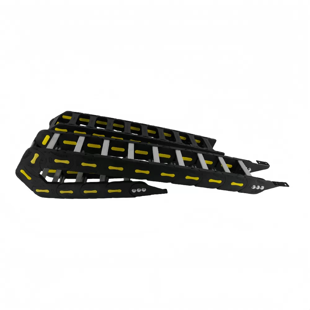
The Physics of High-Speed Cable Carrier Failures
When an automated axis accelerates aggressively, the cable track experiences high shock loads. Two primary physical factors drive dynamic track failure: the polygon effect and asymmetric inertia.
The polygon effect occurs as individual chain links rotate through the bend radius. Because chain links are rigid segments, they do not form a perfect circle. Instead, they form a multi-sided polygon. As each pin enters and leaves the radius, the carrier rises and drops vertically.
At low speeds, this motion is harmless. At 6 m/s, it produces high-frequency vibrations that shake the axis. This vibration rattles guide troughs, generates acoustic noise, and accelerates inner cable fatigue. Choosing a carrier with an optimized link pitch reduces these chordal rise-and-fall shocks.
Asymmetric inertia happens when cables inside the chain shift unevenly. If heavy motor cables rest on one side and light sensor lines sit on the other, the chain twists under acceleration. This torsion causes joint wear and track twisting, which leads to structural link failure.
Step 1: Cable and Hose Cavity Layout (Clearance and Weight Balancing)
Proper internal cavity layout is the foundation of any dynamic drag chain. Cables must never be packed tightly inside the crossbars. As the chain travels through the radius, internal lines need physical freedom to float relative to each other.
The 10% to 20% Clearance Rule
Never size the interior height and width strictly to the outer dimensions of your conduit package. High dynamic acceleration demands strict dynamic drag chain clearance margins:
Pneumatic and Hydraulic Hoses: Allocate at least 15% to 20% clearance between the hose outer diameter (OD) and the crossbar inner height. Hoses expand and contract during pressure cycles.
Electrical Power and Data Cables: Allocate at least 10% clearance around the outer diameter of round electrical cables.
Cavity Cross-Section: The total cross-sectional area of all cables and hoses must not exceed 60% of the total interior cavity area.
Symmetric Balance and Compartment Partitioning
Never allow cables of drastically different diameters to rest on top of each other without vertical shelves. Thicker cables crush thinner sensor lines during dynamic motion.
Always isolate hydraulic lines, pneumatic lines, and electrical lines with vertical interior separators. Place the heaviest cables closest to the outer links or distribute them evenly across the center line. This prevents dynamic roll when the carrier reverses direction at high speed.
Step 2: Calculating the Dynamic Bend Radius
A common error in automation design is picking a plastic cable chain track radius based solely on machine frame space. The carrier bend radius ($R$) must always be determined by the thickest, stiffest cable or hose in your package.
Cable manufacturers specify two bend radii: static and dynamic. Always use the continuous-flex dynamic bend radius.
Flexible Control Cables: Typically require a minimum dynamic bend radius of 7.5 × OD.
High-Flex Motor/Servo Cables: Typically require 10 × OD to 12 × OD.
Pneumatic Tubing: Typically requires 8 × OD to 10 × OD to prevent kinking.
Select a carrier radius equal to or greater than the largest calculated radius in your bundle. For example, if your thickest servo cable has an outer diameter of 18 mm with a dynamic bend factor of 10 × OD:
Minimum Carrier Bend Radius: 18 mm × 10 = 180 mm.
Selecting a smaller radius to save machine space will bend the internal copper conductors past their yield point. This leads to broken conductors and core rupture.
Step 3: Calculating Chain Length and Travel Limits
Once you confirm the bend radius and internal footprint, calculate the overall chain length based on linear stroke.
Chain Length Formula
For horizontal setups where the fixed mounting point sits in the center of the total travel axis, calculate chain length ($L_k$) using this standard formula:
$L_k = \frac{S}{2} + K$
Where:
$S$: Total travel stroke length (in millimeters).
$K$: Curve length allowance ($K = \pi \times R + (2 \times P)$), where $R$ is bend radius and $P$ is chain link pitch.
If the fixed end cannot sit in the middle of travel, calculate the off-center offset:
$L_k = \frac{S}{2} + \Delta M + K$
Where $\Delta M$ is the absolute distance between the center of travel and the actual fixed mounting bracket.
Unsupported Length Dynamics: $FL_g$ vs. $FL_b$
A plastic cable chain track operates horizontally in an unsupported state up to a critical limit. This unsupported zone divides into two operational regions:
Unsupported Straight ($FL_g$): The upper run travels completely straight with zero visible sag. This is the mandatory condition for high-speed, high-acceleration axes ($v > 3 \text{ m/s}$, $a > 8 \text{ m/s}^2$).
Unsupported with Sag ($FL_b$): The upper run displays a controlled sag. Permissible only for low-speed, low-cycle applications.
| Parameter | Unsupported Straight ($FL_g$) | Unsupported Sag ($FL_b$) |
|---|---|---|
| Max Acceleration | Up to 50 m/s² | Less than 5 m/s² |
| Max Speed | Up to 10 m/s | Less than 2 m/s |
| Axis Smoothness | Extremely high | Moderate to poor |
| Wear Rate | Minimal internal stress | Accelerated pin-bore wear |
If your total travel stroke forces the carrier beyond its rated $FL_g$ threshold, the upper run will slap the lower run during acceleration. When this happens, you must integrate an aluminum or steel guide trough system to support the upper run smoothly.
Step 4: Structural and Material Selection for High Dynamics
Standard nylon chains work well in ordinary machinery, but high-velocity operations require specific track geometry and modified polymers. Modern manufacturing setups, including high-output lines supported by QUNHUI systems, rely on structural enhancements to keep the track running predictably.
Short Pitch Engineering
Choose the shortest feasible link pitch for your required interior cross-section. Short-pitch links cycle over the radius smoothly, which minimizes vibration and keeps operating noise below 65 dB(A). They cut peak inertial loads at directional transition points, extending link pin lifespan.
Advanced Polymer Materials
Standard unfilled polyamides absorb moisture, which changes their tensile modulus and causes dynamic sag. For high-speed lines, specify modified materials:
Fiberglass-Reinforced PA66: Increases tensile modulus and prevents carrier deflection over long unsupported spans.
PTFE-Doped Formulations: Lowers the internal friction coefficient between pins and bores, reducing heat build-up.
Anti-Static Additives: Dissipates static electricity generated by rapid rubbing in automated environments.
Strain Relief Infrastructure
Without secure strain relief, your cables will pull inward or bunch up inside the bend radius. Anchor every single cable at both ends of the chain using tiewrap plates, profile rail clamps, or comb-style strain relief blocks.
Position strain relief anchors outside the dynamic bend profile. Maintain a straight distance equal to at least 20 to 30 times the cable diameter between the strain relief clamp and the final articulating link.
Particulate Control and Cleanroom Standards
In semiconductor and lithium-ion battery manufacturing, standard carrier pin-and-bore friction creates airborne micro-debris. For cleanroom environments, pick an ISO Class 1 or Class 2 compliant plastic cable chain track.
These specialized designs replace open sliding pin joints with wear-resistant, enclosed elastomeric joints. This design stops plastic-on-plastic abrasion and prevents line contamination.
High-Acceleration Scenarios: When $a > 20 \text{ m/s}^2$
Linear motor gantries often accelerate past 20 m/s². In this extreme operational envelope, normal sizing calculations are insufficient.
Use these concrete methods to protect the carrier assembly:
Reduce Total Fill Weight: Replace heavy rubber-jacketed cables with thin-wall, high-performance PUR (polyurethane) insulation jackets.
Inverted Glide Arrangements: For long travels running past unsupported limits, install roller-link chains where rolling friction replaces sliding friction. This reduces motor drive force by up to 57%.
Split Carrier Systems: If the utility package is heavy, install two smaller, opposing cable tracks rather than a single massive, wide carrier. This halves the dynamic moving mass on the main carriage.
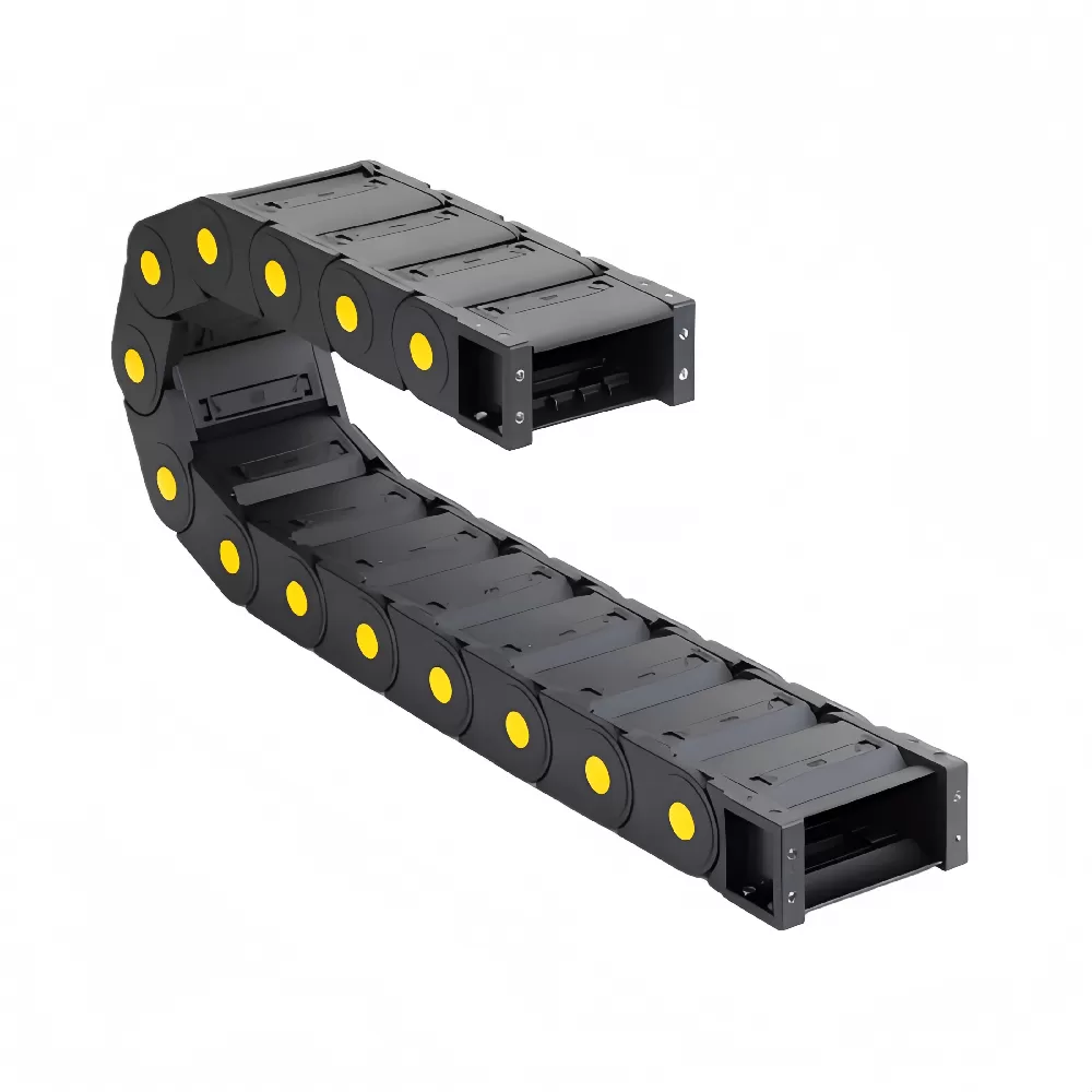
Engineering Resources: CAD and Sizing Software
Designing a dynamic drag chain setup requires checking physical clearances, center-of-gravity offsets, and service life curves. Our engineering portal provides tools to streamline this process:
Downloadable CAD Library: Access native 3D solid models for popular carrier formats, mounting brackets, and dividers.
Dynamic Life Sizing Calculators: Enter your axis stroke, velocity, fill weight, and acceleration to quickly output required bend radius, pin shear stress, and $FL_g$ safety factors.
Frequently Asked Questions
Q1: What happens if the dynamic bend radius is set too tight?
A1: Setting a bend radius tighter than the cable specification causes rapid copper work-hardening. Internal conductors break, shields tear, and the outer jacket blisters. The carrier itself will also suffer high pin-stress loads, cutting overall fatigue life.
Q2: How do you eliminate the polygon effect in high-speed gantries?
A2: Specify a small-pitch plastic cable chain track. Shorter links minimize vertical displacement as pins rotate into the radius. This dampens dynamic vibration, lowers operating noise, and protects sensitive sensors mounted on the moving carriage.
Q3: Can electrical power cables and pneumatic lines share the same compartment?
A3: No. Pneumatic hoses continuously pulse, swell, and move sideways under pressure cycles. If left unseparated, they abrade softer electrical cables. Always place vertical dividers between electrical lines and pneumatic lines, and separate cables with different jacket materials.
Q4: When should an engineer switch from an unsupported setup to a guide trough?
A4: Switch to a guide trough whenever travel length exceeds the unsupported straight limit ($FL_g$) of the selected chain, or whenever horizontal travel exceeds roughly 2.5 to 3 meters under rapid acceleration. The trough keeps the carrier aligned and stops the upper run from whipping sideways.
Q5: What is the ideal strain relief distance from the chain end bracket?
A5: Position strain relief clamps directly behind the carrier mounting bracket. Maintain a distance of roughly 25 to 30 times the cable outside diameter to let lines settle without mechanical pre-stress. The cable must not touch the mounting bracket crossbars under tension.
Specify Your Cable Carrier with Confidence
Properly specifying your high-speed carrier requires checking every detail: clearance margins, bend radius targets, dynamic unsupported lengths, and wear-resistant materials. Getting these variables right guarantees millions of maintenance-free cycles and prevents costly cable failures.
QUNHUI manufactures high-performance plastic cable chain track systems built for demanding industrial automation setups. Our technical team is ready to review your motion profile and deliver a calculated sizing package for your next project.
Send your stroke, speed, and cable schedule to our technical team today. We will supply full calculation sheets, 2D/3D models, and physical test samples within 2 business hours.