

Every second of CNC machine downtime eats directly into operational profit. In high-speed machining centers, a premature cable failure rarely stems from electrical faults alone. More often, mechanical fatigue, chip abrasion, or improper bend geometry destroys cables from the inside out.
Standard off-the-shelf carriers fail when pushed beyond standard operating parameters. That is why choosing an application-matched cable track system is critical for plant reliability. QUNHUI delivers high-performance cable management systems built to survive intense acceleration, heavy hydraulic loads, and abrasive debris.
If you are looking for a reliable drag chain for sale that fits unique dynamic envelopes, custom configuration is the most cost-effective path forward. This guide examines how targeted mechanical design eliminates cable failure and maintains continuous machine uptime.
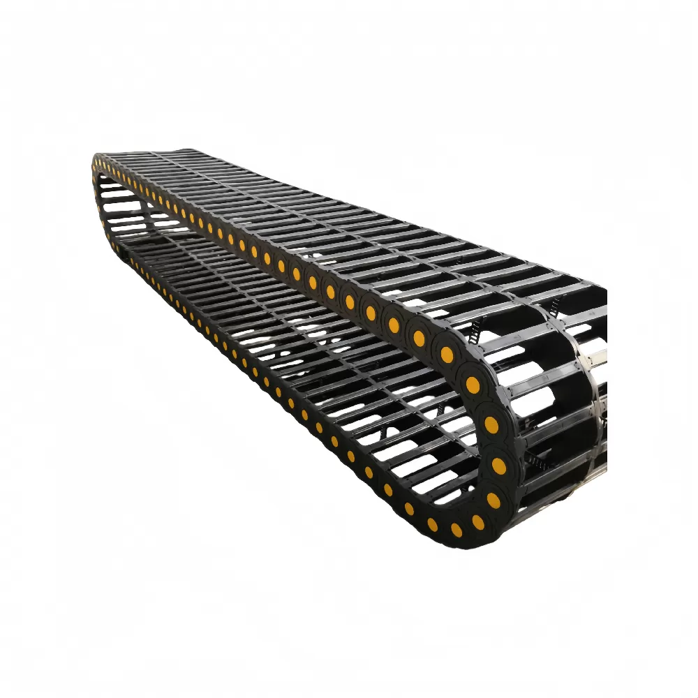
Why Standard Off-the-Shelf Drag Chains Fail in Modern CNC Applications
Modern CNC machining centers run at aggressive feed rates, often exceeding 60 meters per minute with accelerations beyond 1.5G. At these speeds, standard lightweight energy tracks flex, twist, and whip. Dynamic deflection causes internal cables to slap against link interiors, stripping jacketing and breaking copper conductors.
Standard catalog units also fall short when handling hostile operating environments:
Hot Metal Chips: Sharp aluminum, steel, or cast iron chips slice through open bridge carriers and melt into thin plastic frames.
Corrosive Cutting Fluids: Synthetic coolants and aggressive chemical lubricants degrade low-grade plastics, making them brittle within months.
Multi-Axis Inertia: High-speed 5-axis tool centers exert complex torsional loads that snap standard link pins.
Severe Vibration: Aggressive roughing cycles transfer harmonic resonance into the cable carrier, shaking loose standard snap-together link components.
Investing in a custom-engineered cable carrier eliminates these failure points before the machinery leaves the assembly floor. Custom units reinforce high-stress pivot pins, seal out debris, and maintain absolute structural alignment across long travel strokes.
Material Customization: Reinforced PA66 vs. Steel and Aluminum
Matching carrier material to your specific factory environment is the first step in sizing an effective cable track. Industrial environments demand different mechanical properties depending on mass, speed, and environmental contaminants.
Engineering Plastic: Modified Polyamide (PA66)
Polyamide 66 reinforced with glass fiber is the industry benchmark for dynamic, high-speed automation. Our engineered PA66 formulations deliver high tensile strength while maintaining the elasticity required for continuous flexure.
Low Inertia: Lightweight plastic links reduce motor load on high-speed CNC gantries and pick-and-place arms.
Quiet Operation: Built-in dampening pads absorb link impact noise, keeping sound emissions well below 65 dB(A).
Corrosion Resistance: Inert polymers resist cutting oils, mild acids, and industrial solvents without swelling or cracking.
Steel and Aluminum Hybrid Cable Tracks
When environmental conditions exceed the thermal and mechanical limits of polymers, heavy-duty steel and aluminum carriers take over. These systems dominate in heavy gantry mills, hot-rolling mills, and large-span boring machines.
Extreme Thermal Resistance: Steel tracks withstand direct contact with red-hot chips and radiant furnace heat without deformation.
Massive Unsupported Lengths: Galvanized or stainless steel side bands provide exceptional rigidity, supporting heavy hydraulic lines over long travels without sagging.
Custom Machined Aluminum Stays: Precision-drilled aluminum crossbars separate heavy cables into isolated chambers, preventing internal friction and wear.
Structural Configurations: Balancing Accessibility and Protection
Selecting the right carrier structure determines both cable lifespan and maintenance ease. We manufacture three primary structural styles designed for different operational realities.
Open Bridge Cable Carriers
Bridge-style carriers use crossbars with quick-release snap mechanisms on both the inner and outer radius. These units provide maximum heat dissipation for power cables that generate substantial thermal loads during rapid duty cycles.
Open bridge designs are ideal for woodworking routers, automated assembly lines, and dry industrial environments. Maintenance crews can inspect, install, or replace cables quickly without disconnecting system wiring or dismounting the entire track.
Fully Enclosed Chip-Proof Drag Chains
Enclosed cable tubes use interlocking covers to form a protective barrier around sensitive communication lines, servo cables, and pneumatic hoses. These units are necessary for metal-cutting CNC lathes and vertical machining centers.
The smooth outer shell sheds metal chips, grinding dust, and pressurized coolant streams. Precision-sealed link joints stop fine particulate from penetrating the link hinge, preventing abrasive wear at the carrier pivot points.
Multi-Axis 3D Robotic Cable Management
Standard linear carriers handle single-axis travel. Multi-axis articulating machines require omnidirectional flexibility. Our spherical link designs twist smoothly along the robotic wrist, maintaining minimum bend radii across 6-axis articulation paths without binding.
Engineering Sizing Guide: Mathematical Selection for Zero Cable Wear
Sizing an industrial cable carrier requires more than matching internal dimensions to cable diameters. Proper mechanical engineering prevents premature internal wear and dynamic buckling.
1. The Internal Clearance Rule (10% to 15% Clearance)
Cables and hoses must move freely within the carrier interior. As cables bend under tension, their cross-sectional profile shifts slightly. Bundling them tightly guarantees internal friction and jacket failure.
Always maintain a minimum clearance allowance for internal contents:
For round electrical cables: Add at least 10% of the cable diameter as clearance space on all sides.
For hydraulic and pneumatic hoses: Add at least 15% to 20% clearance to allow for dynamic expansion under pressure pulses.
Formula for minimum internal height (Hi): Hi > d_max + (0.10 × d_max), where d_max is the outer diameter of the thickest cable.
Always install vertical and horizontal interior separators. Separators isolate high-voltage power lines from sensitive low-voltage feedback lines, preventing electrical crosstalk while stopping cables from crossing over one another during high-speed reversals.
2. Calculating the Optimal Bending Radius (R)
Selecting a bending radius that is too tight causes copper strand work-hardening, jacket wrinkling, and core failure. Selecting an excessively large radius wastes valuable machine frame envelope space.
To establish the safe bending radius (R) for your drag chain system, identify the maximum cable diameter and the manufacturer's recommended bend rating:
Standard flexible cables: R ≥ 8 to 10 × outer cable diameter.
High-flex continuous-motion continuous-flex cables: R ≥ 6.5 to 7.5 × outer cable diameter.
Rigid hydraulic hoses: R ≥ 12 to 15 × outer hose diameter.
The total carrier bending radius must match or exceed the requirement of the most rigid cable or hose in the package. Choosing the proper radius maximizes the continuous flex life of your internal wiring harness.
3. Managing Travel Distance: Unsupported vs. Gliding Applications
Every cable carrier has an unsupported length limit—the distance the upper run can travel without sagging onto the lower run. This threshold depends directly on the combined weight of the carrier and its contents (fill weight in kg/m).
Unsupported Travel: Used for short to medium travel strokes. The carrier operates quietly without guide channels. The upper run remains straight or shows a slight, engineered camber curve. This configuration handles the highest speeds and accelerations.
Gliding Travel: For extended travel runs exceeding 6 to 8 meters, the carrier upper run glides directly back over the lower run. This installation requires a continuous guide trough to prevent lateral wander and link missteps. Gliding configurations require specialized glide shoes or rollers to minimize friction and wear on the carrier links.
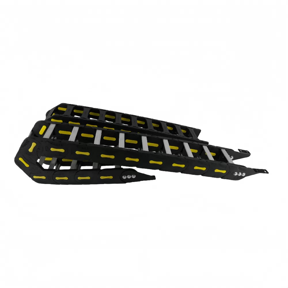
Production Standards and Testing Rigor at QUNHUI
When searching for a drag chain for sale, build quality and material integrity determine long-term operating costs. At QUNHUI, we treat cable protection as a critical branch of industrial machinery design, not an afterthought accessory.
Our production facilities utilize modern injection molding equipment and automated assembly systems. We implement strict quality controls at every stage of the manufacturing cycle:
Raw Material Control: We inspect every batch of virgin polyamide 66 resin for uniform molecular weight, impact resistance, and moisture content before production starts.
Dynamic Fatigue Testing: Production samples run on custom linear test rigs through 10,000,000 continuous cycles at accelerations up to 2G to verify pivot joint integrity.
Tensile and Shear Analysis: Pin connections undergo destructive shear testing to confirm maximum push-pull tensile ratings under heavy payloads.
Environmental Stress Validation: High-temperature and chemical exposure chambers confirm material stability against modern industrial coolants.
Our complete manufacturing process complies with ISO9001 quality management protocols. Finished components carry CE and RoHS compliance certifications, giving international OEMs full regulatory confidence when exporting completed machine tools.
Procurement Guide for Automation Integrators and OEMs
Procuring custom components should never compromise production build schedules. Equipment builders need clear engineering handshakes, short prototype turnarounds, and reliable production pricing.
Customization does not mean long lead times. Using modular mold sets and adaptable extrusion tooling, our engineering team supplies custom CAD files within hours and physical evaluation prototypes within 3 to 5 business days.
For high-volume machine builders, we provide tiered contract pricing structures. Standardizing on common carrier cross-sections across multiple machine configurations cuts unit costs, simplifies maintenance inventory, and guarantees replacement link availability for downstream customers.
Frequently Asked Questions
Q1: What is the typical service life of an industrial CNC drag
chain?
A1: An engineered cable carrier operating within its
specified payload, acceleration, and bend parameters typically achieves between
8,000,000 and 15,000,000 motion cycles. Actual service life depends heavily on
operational cleanliness, operating speeds, and whether the internal cables are
properly separated with sufficient internal clearance.
Q2: How do I measure an existing machine carrier to order an exact
replacement?
A2: Measure the internal height (Hi) and internal width
(Bi) to verify capacity. Next, measure the outer height (Ha) and outer width
(Ba) to confirm external clearance inside the machine chassis. Finally,
determine the bending radius (R) by measuring the total curve height (H) when
the chain is bent into a U-shape, using the formula: R = (H - Ha) / 2. Count the
total link segments or measure the total length from mounting bracket to
mounting bracket.
Q3: What are the minimum order quantities (MOQ) and lead times for
custom-sized drag chains?
A3: We support equipment builders with
flexible order quantities. Standard modular configurations have no minimum order
threshold, while fully custom dimensional builds typically start at an MOQ of 1
to 5 units for testing and validation. Prototype samples ship in 3 to 5 business
days, and volume production batches complete within 2 to 3 weeks.
Q4: Can electrical power cables and pneumatic air lines share the
same drag chain?
A4: Yes, provided they are isolated using vertical
interior dividers or horizontal shelving. Pneumatic hoses expand and contract
during pressure changes, which can rub against and strip the jackets of
sensitive communication and power lines. Isolating different utility lines
within separate interior compartments prevents cross-wear and operational
interference.
Q5: When should I choose a totally enclosed cable carrier instead of
an open bridge style?
A5: Choose an enclosed carrier whenever your
machinery produces chips, abrasive dust, or directed liquid coolant spray. Metal
cutting centers, graphite machining setups, and woodworking equipment require
enclosed designs to shield cables from physical damage. Choose open bridge
carriers when maximum ventilation, low moving weight, and quick visual cable
inspections are your operational priorities.
Request Custom Engineering Support and Direct Pricing
Do not let poor cable routing compromise the reliability of your automated equipment. Whether you are upgrading an active CNC milling machine or engineering a new high-speed gantry system from scratch, custom cable tracks protect your operational uptime.
QUNHUI supplies durable, field-tested cable carriers customized to your exact payload, travel speed, and dynamic requirements. Our engineering team reviews dynamic envelopes, runs bend radius checks, and supplies native 3D CAD models directly to your design department.
Contact our technical team today with your travel length, cable schedule, and operating conditions. We will provide detailed engineering drawings and a direct tiered quote within two hours.