
Linear feed rates exceeding 60 meters per minute, multi-axis simultaneous articulation, and aggressive chemical environments define modern subtractive manufacturing. Within this operational framework, the delivery of electrical power, sensory feedback, pneumatic pressure, and cutting fluids must remain uninterrupted. Automated machine tools rely on specialized conduit architectures to isolate dynamic lines from destructive external forces while preventing continuous flex fatigue. Specifying the correct drag chain for cnc equipment directly dictates the operational availability, mean time between failures (MTBF), and deterministic precision of high-speed machining centers.
Mechanical Kinematics and Dynamic Load Bearing
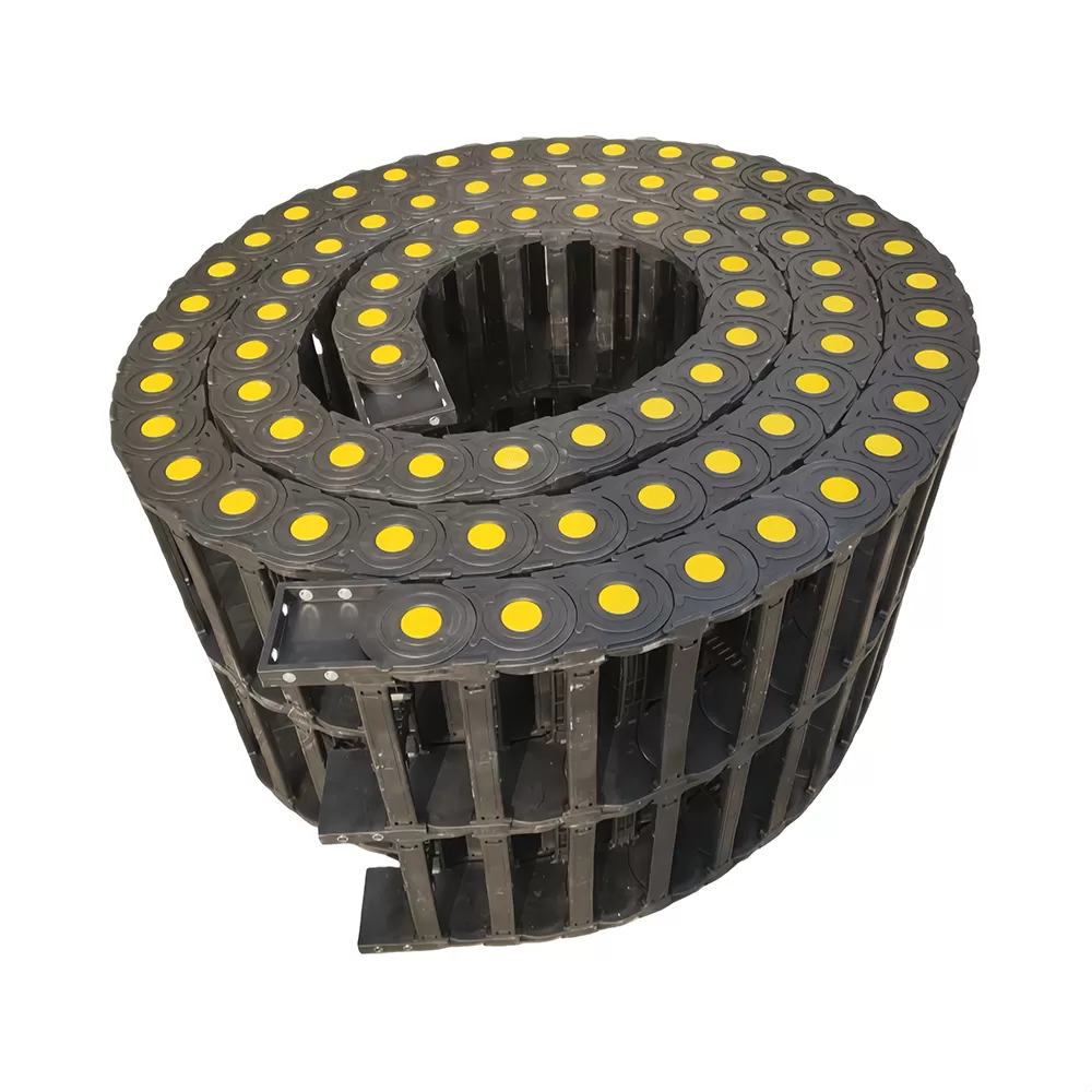
Every axis movement introduces kinetic stress into flexible cables and hoses. As axes cycle through complex tool paths, cables experience continuous tension, compression, and shear forces. Without guided spatial containment, inertia causes trailing lines to whip, rub against casting surfaces, or become pinched in the machine envelope. A dynamic drag chain for cnc machinery transforms an uncontrolled bundle of flexible lines into an articulated, structurally predictable kinematic system.
The mechanical efficiency of a carrier system rests on link articulation geometry. Modern designs rely on a sequence of dual-stop injection-molded links that mechanically constrain angular deflection. These physical travel limits define the minimum bending radius of the entire assembly, eliminating the possibility of bending cables tighter than the parameters specified by cable manufacturers.
Linear acceleration curves introduce dynamic loads that push materials to their limits. High-speed gantries encounter acceleration profiles surpassing 2G, generating significant shear forces on connecting hinge pins. Quality carrier architectures distribute these stresses across broad, precision-machined contact areas within the tongue-and-groove hinge joints, avoiding localized stress risers and early structural failure.
High-duty cycles demand precise control over system pitch. Short-pitch designs incorporate a higher link count per linear meter, dampening the polygonal effect during articulation. This mechanical damping reduces dynamic harmonic vibrations, minimizes operating decibels at high feed rates, and yields smoother motion transmission along linear drive axes.
Material Sciences: Polyamide Composites Versus Alloy Structures
Material selection governs tensile performance, impact resistance, and dynamic service life across diverse shop environments. Selecting between engineered polymers and metallic alloys requires balancing environmental chemistry against mechanical loading requirements.
Fiberglass-reinforced polyamides, specifically PA6 and PA66 variations, constitute the industry benchmark for standard to high-speed axis assemblies. Glass fiber loadings ranging from 15% to 35% substantially enhance tensile modulus, creep resistance, and dimensional stability across wide operating temperature envelopes. Engineering suppliers such as QUNHUI engineer advanced composite blends formulated to resist continuous chemical degradation from synthetic dielectrics, semi-synthetic emulsions, and oil-based coolants.
Galvanized steel and stainless steel constructions serve specialized heavy-duty functions where thermal extremes and direct structural abuse exceed polymer thresholds. High-capacity boring mills, heavy foundry machinery, and large horizontal lathes handling mass volumes of sharp steel turnings benefit from metal carriers. Steel provides unmatched resistance to hot, sharp chip strikes, though it introduces substantial deadweight that limits dynamic acceleration and demands more powerful drive motors.
Modified Polyamide (PA66-GF): Low tare weight, high dynamic speed up to 10 m/s, integrated vibration dampening, low friction coefficient, high resistance to cooling fluids.
Hybrid Composite-Aluminum: Polyamide side links paired with machined aluminum crossbars, combining dynamic weight optimization with wide internal spanning capability.
Machined Carbon Steel / Stainless Steel: Outstanding mechanical strength, complete immunity to red-hot flying chips up to 1000°C, high torsional load capacity, suitable for heavy hydraulic umbilical systems.
Kinematic Calculations and Structural Sizing Protocols
Improper sizing remains a prevalent source of early harness failure. Specifying an industrial drag chain for cnc axes requires rigorous calculation across multiple mechanical variables, beginning with the dynamic load calculation.
Total system load integrates the bare mass of the chain links with the cumulative weight per meter of all housed conductors, servo encoder lines, fluid conduits, and pneumatic tubes. This composite value ($q$, expressed in kg/m) defines whether the carrier will operate within an unsupported length envelope or require secondary structural guide troughs.
The unsupported length ($L_{un}$) represents the maximum horizontal travel distance over which the upper run of the carrier glides without contacting the lower run or intermediate support structures. This metric is divided into two distinct operating zones: unsupported straight ($F_L$), where the upper run maintains positive camber without measurable sag, and unsupported with permissible sag ($F_B$). Operating within the straight parameter ensures maximum service life and minimizes dynamic harmonic bounce during directional reversals.
Bending radius ($R$) calculation requires deep analysis of the largest cable
or hose in the dynamic bundle. While individual conductors may specify a dynamic
radius of $7.5 \times d$ (where $d$ is external cable diameter), conservative
machine tool design protocols dictate a safety multiplier:
$R \ge 10
\times d \text{ (Electrical conductors)}$
$R \ge 12 \times d \text{
(Shielded data and servo feedback lines)}$
$R \ge 15 \times d \text{
(Hydraulic high-pressure hoses)}$
Selecting a carrier radius that
accommodates the most restrictive internal line prevents premature core
shearing, shielding braid fatigue, and hydraulic sheath friction.
Internal Cavity Architecture and Separation Strategies
Dynamic friction within the carrier cavity accounts for significant internal wire fatigue. Lines shifting unpredictably during high-velocity directional changes rub against neighboring jackets, leading to wear, jacket splitting, and short circuits. Proper separation design stabilizes lines along the neutral axis.
Lines must occupy assigned partitions using vertical separators and horizontal shelf splitters. The golden engineering rule for cavity distribution mandates that no line exceed an operational weight differential of 2:1 compared to adjacent lines without mechanical compartmentalization. Combining heavy hydraulic supply lines alongside ultra-sensitive digital bus cables within an undivided compartment causes mass-differential friction, generating signal distortion and early outer-jacket failure.
Clearance Margins: Cables require dynamic clearance. Circular lines demand a minimum of 10% radial clearance calculated against the outer jacket diameter relative to the compartment boundary. Fluid lines require 20% radial clearance to permit volumetric expansion under cyclic operational pressure.
Symmetrical Mass Distribution: Place heavier hydraulic lines toward the outer flanks of the carrier cavity and lighter sensory cables toward the center line. This structural layout preserves dynamic balance, preventing lateral roll and localized hinge pin fatigue.
Neutral Axis Retention: Clamp cables securely at both fixed and moving ends using comb-style strain relief brackets. The cables must lay untwisted along the neutral bending axis of the carrier, free from axial pretension or compressive stress.
Contaminant Mitigation: Swarf, Coolants, and High-Speed Environmental Defense
Toolroom machinery produces hostile micro-environments. Milling spindles launch sharp carbide, hardened steel, or cast iron chips alongside high-pressure, flood-applied cooling streams. In vertical machining centers and multi-axis turn-mill configurations, the cable track frequently operates inside this primary processing envelope.
Standard open-frame carriers permit swarf penetration. Entrained metal chips lodge between consecutive articulation stops, blocking the designed radius, forcing the upper run out of alignment, and mechanically cutting exposed cables. Precision machine tool engineering necessitates using an enclosed drag chain for cnc operations within the working envelope.
Enclosed crossbars create continuous interlocking shields that shed flying chips and deflect direct fluid jets. These dynamic covers preserve continuous, tight overlap across the entire travel cycle without binding. Manufacturers such as QUNHUI engineer advanced snap-fit enclosed carriers featuring smooth external contours that reject chip buildup, ensuring debris glides away via standard chip evacuation augers rather than settling on articulation pins.
When axis travels extend beyond the unsupported limit—typically exceeding 3 to 4 meters depending on total fill weight—the upper run glides along the lower run. In these extended travels, specialized guide troughs are necessary. Precision-aligned troughs prevent the carrier from migrating laterally, guiding long-travel horizontal axes through smooth cycles and eliminating twisting forces along the chain links.
Diagnostic Failure Analysis and Maintenance Methodologies
Preventative engineering demands recognizing premature wear indicators before structural failure prompts unexpected machine tool downtime. Systematic wear patterns reveal underlying mechanical misalignments or dynamic overloads across the assembly.
Lateral hinge wear indicates misalignment between the moving tow-arm mount and the fixed machine bed anchor. When these two mounting interfaces deviate by mere fractions of a degree, the articulated chain operates under continuous torsional loading. Torsion forces the hinge pins to experience asymmetric wear, leading to link separation, excessive snake-like lateral deflection, and catastrophic tracking derailment.
Pronounced sagging along the upper run points to hinge pin deformation, structural overfilling, or exceeding the rated dynamic loading profile. Once positive camber degrades into noticeable negative sag, the carrier draws high dynamic current on the drive axis, causing localized vibration and triggering drive overload alarms on high-feed CNC controls.
Continuous condition monitoring and predictive inspection intervals eliminate these risks. Machine tool maintenance frameworks should include quarterly visual inspections of the articulation stops, check for foreign body intrusion within the pin pockets, inspect internal separators for dynamic shifting, and verify strain relief integrity at both mounting terminals.
Custom Dynamic Specifications for High-Demand Axis Systems
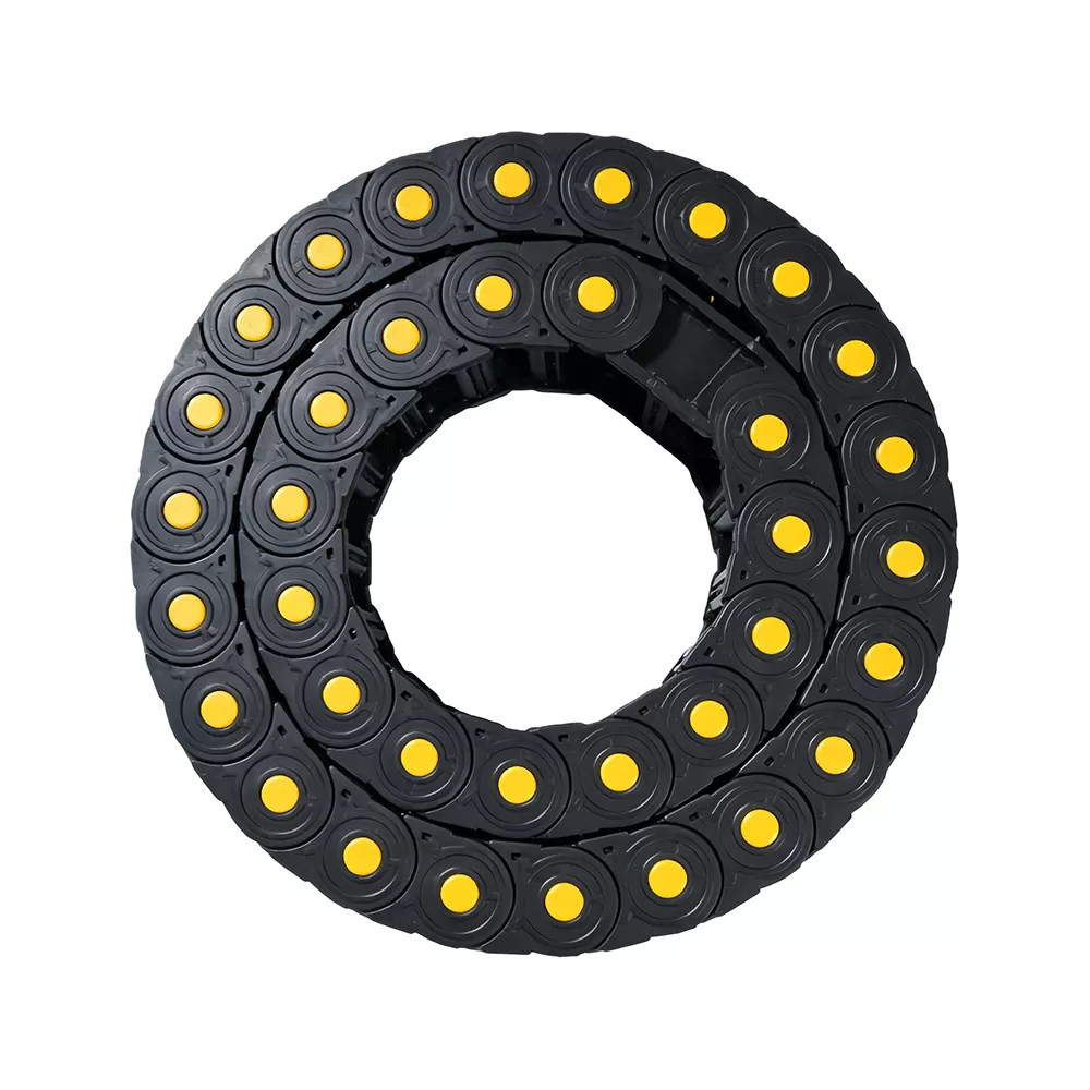
Complex machine tools—such as 5-axis simultaneous machining centers, bridge gantry mills, and heavy-duty horizontal boring machines—frequently present unique kinematic envelopes that standard catalog assemblies cannot reliably manage. Factors such as vertical hanging heights, secondary reverse bend radius (RBR) loops, and multi-axis rotational arcs require custom-designed carrier architectures.
Vertical suspended applications introduce dynamic tensile stresses along every link pin, requiring specialized locking pins and bracket structures to counter gravitational loads. Conversely, high-acceleration robotic tool-changers demand lightweight composite carriers engineered with carbon-fiber infusions to minimize rotational inertia.
Partnering with experienced engineering specialists guarantees balanced kinematic management across every dynamic axis. Specialized production facilities, such as those maintained by QUNHUI, can custom-mold specific radius combinations, deploy integrated aluminum mounting interfaces, and configure application-specific internal containment layouts. This custom component development ensures the drag chain for cnc integration supports uninterrupted production schedules across multi-shift operational environments.
Technical Inquiries: Frequently Asked Questions
How is the correct interior height of a cable carrier determined?
Interior height ($H_i$) depends directly on the single thickest cable or hose inside the dynamic bundle, plus an engineering clearance factor. Apply a minimum safety factor of 10% to 20% on top of the largest cable's outer diameter. For example, if the largest hydraulic line measures 25 mm in diameter, the minimum interior chain height must equal at least 28.5 mm to 30 mm to prevent internal jacket friction during dynamic movement.
What causes continuous-flex cables to develop a corkscrew failure inside the carrier?
Corkscrewing happens when cables are twisted along their longitudinal axis during assembly or when they lack adequate operational clearance within internal compartments. Cables must be unrolled tangentially from packaging reels—never pulled vertically over the flange. Furthermore, dynamic lines must float freely through the carrier neutral axis without clamping inside intermediate partitions, anchored only at the extreme terminal points via proper strain relief fixtures.
When should an enclosed cable carrier be chosen over an open-bracket design?
Open-frame designs offer superior thermal dissipation and lightweight operation, making them optimal for external machine axes or sealed service raceways. Choose an enclosed tube structure whenever the carrier operates within the direct swarf discharge zone, near cutting fluid spray trajectories, or adjacent to hot turning operations where flying metal turnings would settle between open link joints.
What defines the difference between unsupported straight ($F_L$) and unsupported with sag ($F_B$)?
Unsupported straight refers to operation where the upper run maintains positive design camber, riding flat or slightly elevated without downward deflection. Unsupported with sag occurs when dynamic weight forces the upper run to sag downward below the mounting plane. Operating in $F_L$ mode allows maximum acceleration, highest cycle life, and low operating noise. Modern CNC feed systems should be engineered to maintain $F_L$ conditions whenever space envelopes permit.
Can electrical servo lines and fluid delivery conduits share the same carrier cavity?
They can occupy the same overall carrier assembly, provided they are physically segregated using vertical and horizontal dividers. Hydraulic and pneumatic hoses undergo volumetric expansion, dynamic pressure spikes, and generate thermal energy during machine operation. They must never touch sensitive motor power or digital encoder lines, as continuous rubbing will shear outer jacketing and cause dynamic electrical faults.
Engineering Consultation and Specialized Inquiries
Machine tool accuracy relies on structural dependability across all sub-assemblies. Protect your axes from unexpected downtime by deploying dynamic cable protection engineered to match your exact stroke lengths, acceleration curves, and chemical exposure parameters. Submit your complete system load profiles, axis geometries, and dimensional constraints to our senior engineering application team for dynamic load calculation, 3D kinematic modeling, and comprehensive quotation services.