
Dynamic cable and fluid line protection remains one of the most mechanically demanding facets of high-speed automation and computer numerical control (CNC) equipment. As multi-axis machining centers advance in acceleration profiles—routinely exceeding 2G—and linear velocities reach upward of 5 meters per second, the conduits routing hydraulic lines, pneumatic feeds, fiber optics, and servo power cables encounter immense dynamic stress. Within this operational matrix, the drag link chain serves as the mechanical backbone, establishing a controlled bend radius, absorbing tensile and torsional inertia, and preventing premature conductor failure. Selecting, configuring, and maintaining these linkages requires a granular understanding of kinematics, polymer tribology, and mechanical interference parameters.
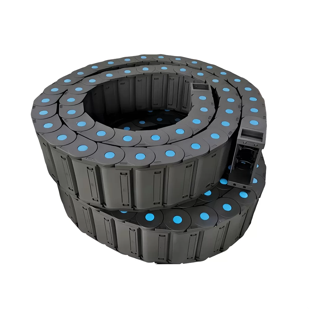
Kinematic Mechanics and Structural Anatomy of Dynamic Link Assemblies
Every dynamic articulated carrier operates via an interdependent series of interlocking modular segments. Each segment contains pivot points, mechanical stop-dogs, crossbars, and lateral sidebands that determine the chain's structural envelope. The fundamental role of the individual segment is to limit the flexural arc of internal conductors to a predetermined radius, thereby maintaining the bending envelope above the minimum threshold specified by cable and hose manufacturers.
The operational geometry relies heavily on the stop-dog mechanism within the link junction. As the assembly transitions between the straight run and the curved deflection zone, internal stop faces engage to eliminate over-rotation. Under aggressive cyclic loading, these contact zones must disperse substantial compressive forces. If the link pitch is improperly matched to the sprocket pitch or drive velocity, high shock loads ripple across the link pin assemblies, yielding rapid mechanical play and structural droop.
Pitch Dimensioning: A smaller pitch reduces chordal action during articulation, resulting in smoother velocity profiles, suppressed mechanical vibrations, and reduced acoustic output during dynamic cycles.
Neutral Axis Alignment: Cables and fluid lines must rest precisely along the neutral bending axis of the links to eliminate compressive crush forces on the inner radius and severe tensile strain on the outer radius.
Lateral Rigidity: Interlocking tongue-and-groove joints along the lateral boundary distribute side-load forces, mitigating lateral deflection when machines execute rapid orthogonal direction changes.
Material Formulations: Structural Polymers Versus High-Tensile Alloys
Environmental conditions dictate whether an assembly should be fabricated from engineered polymers, pressed carbon steels, or high-tensile stainless alloys. Modern manufacturing environments increasingly depend on reinforced polymer composites, though heavy industrial equipment still commands metallic architectures under extreme heat and shock environments.
In high-speed linear gantry and pick-and-place setups, fiberglass-reinforced Polyamide 66 (PA66-GF30) represents the standard matrix. The inclusion of chemically bonded short glass fibers elevates tensile strength, optimizes creep resistance across elevated thermal envelopes, and enhances dynamic elastic modulus. Manufacturers like QUNHUI engineer proprietary compound matrices featuring internal lubricants, such as PTFE micro-particles, to diminish hinge-pin friction during extended reciprocating strokes.
Heavy metallurgy, including galvanized carbon steel and AISI 304 or 316 stainless steel, dominates foundries, steel mills, and offshore drilling platforms. While these systems carry higher physical weight—imposing higher parasitic inertia onto mechanical drives—they possess absolute immunity to continuous hot weld spatter, high-velocity particulate abrasion, and extreme chemical immersion that would degrade synthetic polymers.
Calculating Dynamic Unsupported Length and Sag Envelopes
Determining the mechanical feasibility of an installation involves evaluating the unsupported length of the run. The unsupported length refers to the distance along the upper run from the moving carrier bracket to the initial tangent point of the bend curve, operating without structural support rollers or guide troughs.
This dynamic state is governed by link rigidity, link stop design, and overall fill weight. Total fill weight incorporates the net weight per linear meter of the carrier itself plus the accumulated weight of all housed power cables, sensor lines, pneumatic tubing, and hydraulic fluid columns. Two distinct states define this metric:
Straight Unsupported Run: The upper run exhibits zero measurable sag or displays a slight pre-tension camber above the horizontal plane. This configuration allows peak linear velocity, high accelerations, and maximum service life.
Allowable Sag Run: The structural weight surpasses the initial camber pre-tension, creating a controlled downward deflection along the upper run. Operating within this margin accelerates mechanical hinge fatigue and demands reduced operational speeds.
When the planned stroke length causes the unsupported upper run to exceed structural tolerances, the mechanical design must shift from an unsupported configuration to an active gliding system. Gliding systems route the upper link section directly across the lower link section inside continuous low-friction guide troughs, demanding lateral stabilization shoes and dynamic wear pads to suppress harmonic whip.
Internal Compartmentalization and Dynamic Cable Preservation
Cable longevity within an articulated carrier depends entirely on internal layout discipline. Direct dynamic contact between jacket materials with divergent chemical compositions—such as polyurethane (PUR), polyvinyl chloride (PVC), and thermo-elastomers (TPE)—causes high surface friction, structural heating, and eventual jacket peeling under continuous dynamic cycling.
To eliminate internal friction points, the carrier requires vertical separators, horizontal shelving, and modular lock-pins. These interior components form discrete, isolated chambers for each conductor or fluid line, assuring that dynamic movements remain linear and predictable.
Clearance Margins: Every circular conductor or pneumatic hose requires a minimum radial clearance envelope of 10% to 15% between the outer jacket diameter and the adjacent separator walls to accommodate lateral expansion during mechanical flexing.
Weight Distribution Symmetry: Heavy hydraulic lines and thick power feeds must reside along the outermost lateral edges of the link chamber. Placing dense cables toward the sides minimizes torsional twisting across the longitudinal axis of the chain.
Dynamic Separation of Media: Heavy hydraulic conduits containing fluctuating operating pressures must never share an undivided compartment with delicate optical communication lines or low-voltage sensor wiring to prevent crush loads.
Dynamic Inertia and Vibration Mitigation in CNC Multi-Axis Travel
High-precision multi-axis machining facilities expose dynamic carrier systems to severe compound acceleration curves. In simultaneous 5-axis tool center point (TCP) machining, toolheads execute rapid directional reversals along orthogonal axes. Under these operational regimes, a poorly secured drag link chain induces structural harmonic vibrations that transmit back into the machine chassis, manifesting as surface finish imperfections, chatter marks, and diminished dimensional tolerances on milled surfaces.
Minimizing this dynamic feedback requires dampening the impact energy generated as the chain articulates into its mechanical stop-dogs. Modern high-tier linkages integrate dual-component dampening pads composed of elastomeric polymers co-molded directly into the stop zones. These integrated shock pads absorb the deceleration spikes of each link segment as it straightens, preventing structural shock waves from transferring down the machine base.
Mounting bracket geometry equally dictates dynamic stability. Fixed and moving bracket terminations must align co-linearly with the guide channel path. A misalignment of merely 0.5 degrees introduces asymmetric torsional loading onto the initial three hinge links, initiating accelerated localized stress cracks along the primary pin bores.
Comparative Mechanical Parameters
The selection process requires continuous cross-referencing between geometric spatial constraints and mechanical output parameters. The following matrix illustrates representative structural benchmarks observed across industrial machine assemblies:
| Application Category | Primary Material Base | Maximum Velocity (m/s) | Maximum Acceleration (m/s²) | Typical Unsupported Length (m) |
|---|---|---|---|---|
| High-Speed Laser Cutting Gantry | Reinforced PA66-GF30 | 8.0 – 10.0 | 40.0 – 80.0 | 1.8 – 2.5 |
| Heavy Horizontal Milling Machine | Hybrid Steel-Sleeve Composite | 3.0 – 5.0 | 10.0 – 20.0 | 3.5 – 5.0 |
| Steel Foundry Transfer Crane | Zinc-Plated Heavy Steel | 1.0 – 2.0 | 2.0 – 5.0 | 6.0 – 12.0 (Supported) |
| Cleanroom Semiconductor Handler | Low-Erodible Polyketone (PK) | 2.5 – 4.0 | 15.0 – 25.0 | 1.2 – 1.8 |
Environmental Protection Protocols: Enclosed Profiles Versus Open-Link Frames
Determining whether to deploy an open-link carrier or a fully enclosed dynamic tube involves evaluating the particulate load of the operating envelope. In clean automation lines, automated storage systems, and dry packaging stations, open-frame configurations offer distinct thermal advantages. Open designs facilitate continuous convective heat transfer away from high-capacity power lines and dramatically simplify regular visual inspections of conduit conditions.
Machining centers utilizing flood coolant systems, dynamic mist extraction, or generating flying metal chips demand completely sealed structural tubes. Hot, sharp machining swarf—such as stainless steel spirals or brass fragments—falling directly into open-link carriers can settle between interlocking segments, physically blocking articulation and puncturing outer cable sheaths.
Enclosed crossbar tubes incorporate interlocking cover plates with labyrinth seals. The dynamic seals engineered into robust equipment developed by organizations like QUNHUI prevent cutting fluids, abrasive grinding grit, and fine airborne particulate matter from breaching the internal cavity, preserving critical fluid lines and signal cables over prolonged operational periods.
Tribological Wear Diagnostics and Hinge Pin Maintenance Lifecycle
Preventative maintenance schedules for production machinery frequently focus on spindle bearings, ballscrews, and linear guide blocks while neglecting dynamic line carriers. However, mechanical failure of a dynamic link directly halts production cycles. A thorough diagnostic program focuses on the tribological wear patterns present at the hinge joint.
Over hundreds of thousands of dynamic flex cycles, the mechanical connection between the pin and the receptive bore suffers abrasive friction wear. This wear process manifests through visible bore elongation. As the bore ovalizes, individual link pitch increases incrementally across the entire assembly. This cumulative elongation reduces structural pre-camber, resulting in an observable drop of the upper run toward the lower carrier segment.
Technicians must regularly inspect and clean dynamic track systems:
Monitoring Link Sag: Measure the center-line sag of the unsupported run periodically using laser displacement sensors or manual reference checks. A consistent downward deviation exceeding 5% of the original installation profile indicates advanced pin-joint mechanical wear.
Strain Relief Verifications: Cable clamps positioned at the stationary and moving end brackets must retain their clamping torque. If cables begin sliding through the clamps, tensile forces pull directly on termination plugs, causing terminal pull-out or internal wire necking.
Debris Extraction: Guide channels must remain free of chip accumulation and fluid sludge. Settled debris increases sliding friction during glide travel, overloading linear drive motors and eroding the outer surfaces of bottom-run links.
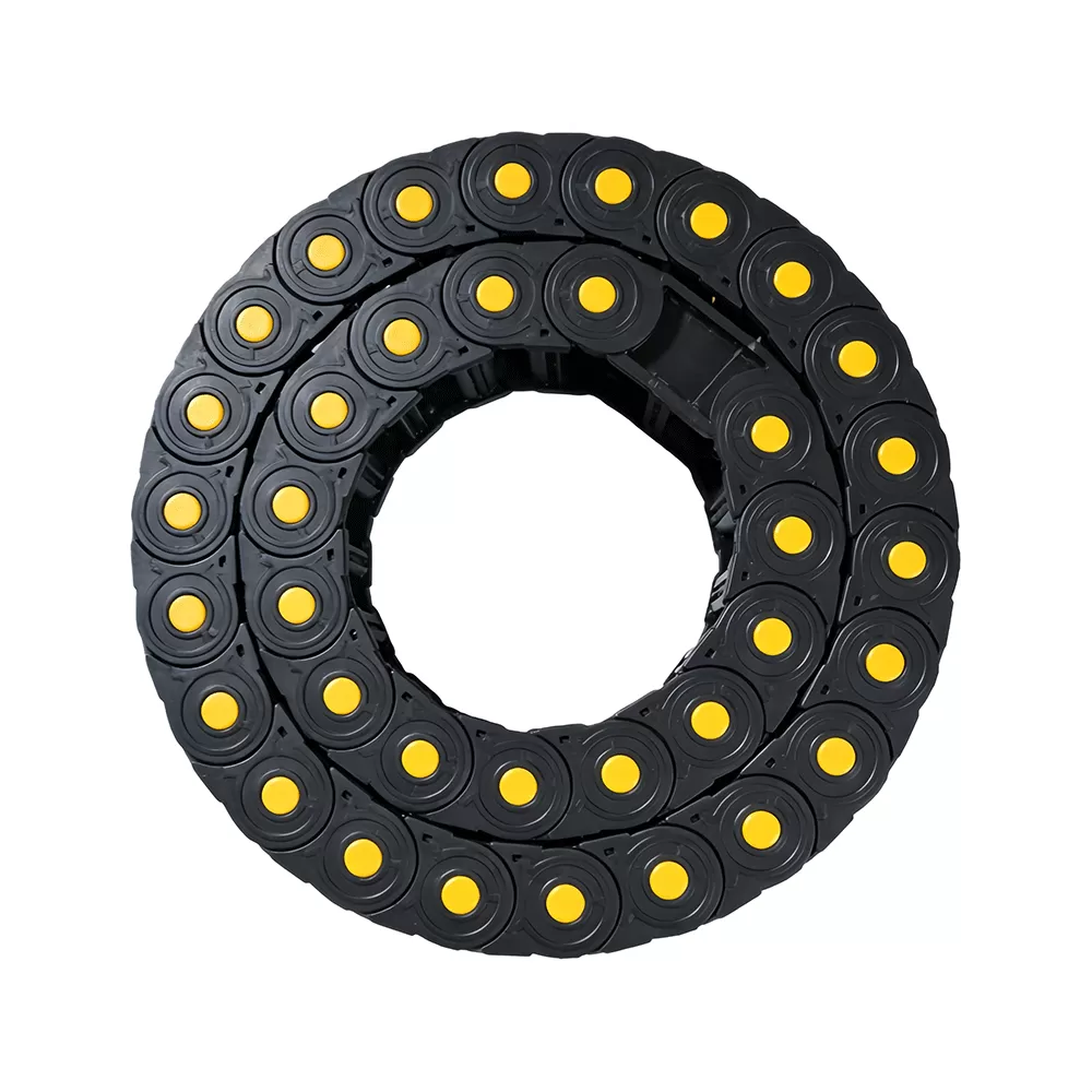
Specialized Implementations in Extreme Operating Scenarios
Certain industrial installations introduce multi-axis rotary movements, long vertical travel paths, or extreme cleanroom mandates that contradict baseline linear sizing protocols. Each scenario requires specialized adaptations to standard kinematics.
In vertical configurations, such as high-bay automated storage cranes or large vertical turret lathes, the drag link chain hangs freely without an unsupported horizontal run. The primary mechanical focus transitions to vertical side-sway dampening and reverse-bend protection. External guide rails must run the entire height of the travel zone to eliminate pendulum swing caused by rapid vertical accelerations and decelerations.
Multi-axis articulation presents another complex boundary. When a robotic arm rotates along a vertical axis while executing horizontal extensions, standard single-axis hinge links bind under torsional deflection. In these multi-directional environments, systems must use three-dimensional spherical linkages or modular continuous flex sheaths designed to distribute axial torsion evenly across every segment, preventing localized stress concentrations.
Cleanroom settings require specialized testing for airborne particulate shedding. As conventional composite links flex, microscopic friction along stop surfaces releases sub-micron plastic debris into the ambient environment. Facilities operating under ISO 14644-1 standards necessitate dynamic systems molded from ultra-low-friction wear-resistant polymers that run quietly, eliminate mechanical abrasion, and meet stringent particulate thresholds without external lubrication oils.
Frequently Asked Questions
What mechanical factors determine the minimum bend radius for an installation?
The minimum bend radius is governed entirely by the thickest or stiffest conductor installed within the internal compartment. As a mechanical standard, the bend radius of the dynamic link chain must match or exceed the maximum bend radius recommended across all housed cables and hoses. For standard dynamic power cables, this value typically equates to 7.5 to 10 times the outer cable diameter, while rigid pneumatic and hydraulic hoses routinely require a bend radius calculated at 10 to 12 times their outer cross-section to prevent kinking.
How is thermal expansion managed in extended plastic link assemblies?
Polyamides naturally exhibit higher linear thermal expansion coefficients than metallic guide troughs. Over long travel installations extending beyond 50 meters, a temperature shift of 20 degrees Celsius yields significant dimensional variances across the chain's length. Mechanical designs compensate for this thermal shift by engineering expansion tolerances into the floating bracket terminals, ensuring the assembly can expand or contract within its guide trough without generating compressive bucking loads.
Why do cables fail from corkscrewing inside dynamic carrier systems?
Corkscrewing describes a failure condition where a multiconductor cable develops helical twists and deformations within the carrier channel, ultimately rupturing its external jacket. This condition stems from improper installation where the cable was pulled off a spool over the flange edge rather than rolled off a rotating drum, introducing baseline torsion. Alternatively, it results from inadequate internal compartmentalization that permits cables to cross over one another during dynamic operation.
What operational limits dictate shifting from an unsupported system to a gliding design?
The transition threshold depends on the combined mass of the chain and its internal payload relative to the total stroke length. When the required stroke exceeds the structural physical limits of the link's pre-tension camber—typically between 3.5 to 6.0 meters for most standard heavy-duty polymer profiles—the upper run physically touches the lower run. At this inflection point, continuous guide troughs equipped with low-friction wear surfaces are mandatory to stabilize the gliding assembly.
How do dynamic carrier assemblies resist aggressive industrial cutting coolants?
Standard synthetic cooling fluids contain chemical additives, bio-inhibitors, and surfactants that can extract plasticizers from common industrial polymers, causing standard plastics to become brittle and crack. Systems operating in direct contact with cooling sprays utilize customized PA66 compounds fortified against chemical hydrolysis, preventing the polymer chains from breaking down under continuous fluid contact.
What methods optimize drag link chain performance under multi-axis torsional loading?
Standard carrier designs only permit articulation along a single rotational axis. Applying torsional stress forces the individual links to twist across their joints, leading to split sidebands and broken stop faces. Mitigating these torsional forces requires implementing rotary-specific carriers mounted within concentric guide housings or transitioning to multi-axis spherical linkage systems engineered specifically to handle continuous 3D angular articulation.
Industrial Technical Consultation and Sizing Inquiries
Selecting the correct dynamic carrier configuration demands precise mathematical evaluation of your operating envelope, including acceleration profiles, total payload weight, atmospheric chemical exposure, and geometric space limits. Supplying your system specifications—such as stroke length, maximum linear velocity, fluid hose pressure requirements, and target bend radiuses—enables our specialized technical team to prepare comprehensive engineering calculations, 3D CAD integration models, and formal quotation packages tailored precisely to your operational requirements.