
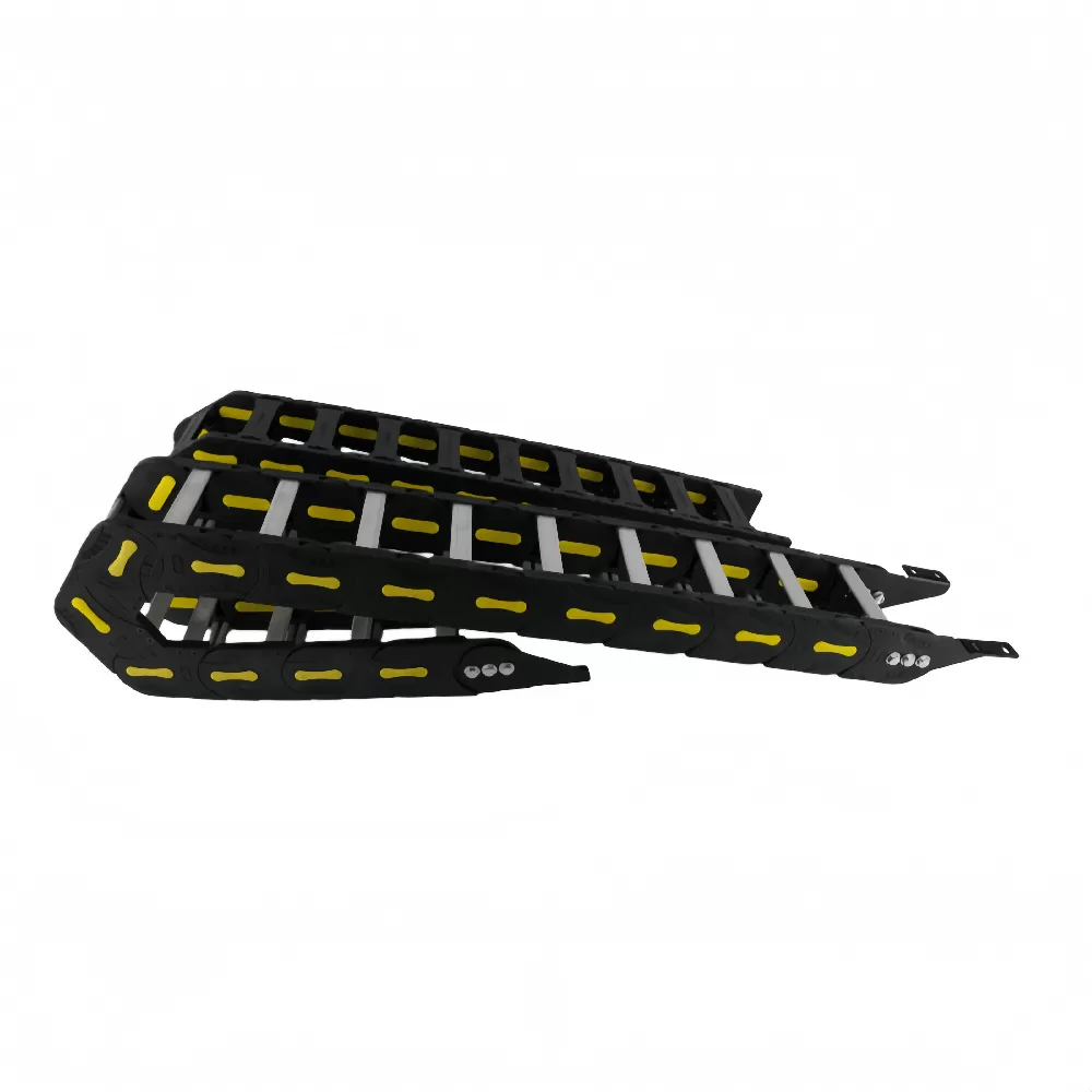
Dynamic automation machinery subjects power, signal, and hydraulic lines to continuous mechanical stresses, including tension, bending fatigue, and abrasion. A properly engineered flexible drag chain (also referred to as an energy chain or dynamic cable carrier) guides and safeguards these lines across linear, rotary, or multi-axis strokes. Selecting the wrong carrier or botching interior clearance rules leads to jacket abrasion, conductor severance (often called "corkscrewing"), and unplanned production downtime.
This technical guide details the mechanical parameters required to specify, size, and integrate a dynamic cable management system that achieves its maximum design lifespan in high-cycle industrial automation.
Core Mechanical Principles: How a Flexible Drag Chain Mitigates Dynamic
Failure
A dynamic carrier isolates internal conduits from external tensile forces, pinch points, and severe inertia. In continuous cycling applications, standard flexible conduit quickly fails because it lacks controlled path constraints and localized radius stops. A high-grade flexible drag chain addresses these failure points through specific structural design elements:
Controlled Bending Radius: Integrated stop-dogs in each link prevent the internal lines from bending past their designated minimum bend radius ($R$), stopping conductor fatigue and hydraulic line kinking.
Neutral Axis Retention: By securing cables along their neutral axis through dedicated interior separation, relative friction between moving lines is virtually eliminated.
Tensile Absorption: High acceleration and deceleration forces (up to $50\text{ m/s}^2$ in advanced pick-and-place robotics) are absorbed entirely by the carrier shell rather than transferred into cable terminations.
Material Selection Matrix: Polyamide vs. Steel Constructions
Matching the chain material to the operating environment dictates wear limits, weight budgets, and total system longevity. Industrial carriers are generally divided into modified thermoplastics and structural metals.
| Material Class | Specific Formulations | Primary Advantages | Operating Limitations |
|---|---|---|---|
| Engineered Polymers | Polyamide 66 (PA66) with 15–30% Glass Fiber reinforcement | Low inertia, self-lubricating hinge pins, high chemical resistance, cleanroom compatibility (ISO Class 1 capable), low acoustic profile. | Susceptible to thermal degradation above 120°C; lower tensile limits on extended, high-fill unsupported spans. |
| Galvanized Carbon Steel | Q235 / Heavy-gauge Cold-Rolled Carbon Sheet | Maximum mechanical payload capacity, high shock resistance, structural rigidity over extended unsupported spans. | High self-weight increases drive motor requirements; susceptible to galvanic corrosion without specialized coatings; higher operational noise. |
| Stainless Steel | AISI 304 / AISI 316 Marine Grade | Extreme corrosion resistance against acids, alkalis, and washdown protocols; broad thermal envelope (-40°C to +400°C). | Substantially higher procurement costs; high tare weight; requires careful pin-lubrication maintenance to prevent galling. |
For modern CNC gantry systems, pick-and-place units, and logistics automation, fiber-reinforced PA66 is the baseline industry standard. Structural steel remains restricted to heavy foundries, offshore drilling rigs, and continuous metal-chip cutting zones.
The Critical Sizing Equations: Calculating Bending Radius and Chain Length
Selecting a drag chain based strictly on outer physical dimensions often causes premature failure. Engineers must size the assembly around the largest cable's bend limits and the travel geometry.
1. Determining Minimum Bending Radius ($R$)
Each cable and hose within the chain has a manufacturer-specified dynamic minimum bend radius. As a general engineering standard:
Standard Dynamic Control Cables: $R \ge 7.5 \times \text{Outer Diameter (OD)}$
Shielded Bus / Data Cables: $R \ge 10 \times \text{OD}$
Hydraulic Lines (High Pressure): $R \ge 12 \times \text{OD}$
Always base the flexible drag chain radius on the largest single cable or hose in the bundle. Undersizing this value quickly degrades internal copper conductors through dynamic work-hardening.
2. Calculating Total Chain Length ($L_k$)
For horizontal travels where the fixed point is placed precisely in the center of the travel stroke ($S$), calculate chain length using the formula:
$L_k = \frac{S}{2} + K$
Where $K$ is the loop length compensation derived from the selected radius ($R$):
$K = \pi \cdot R + (2 \times P)$ (with $P$ representing the individual link pitch length).
If the fixed terminal bracket is placed off-center, add the displacement distance ($\Delta M$) directly to the required chain link calculation.
3. Unsupported Length ($L_s$) vs. Gliding Applications
The unsupported length is the horizontal distance the carrier travels before the upper run sags into the lower run. This depends directly on the combined weight of the carrier and its contents (kg/m). Once a travel length exceeds the carrier's unsupported threshold ($F_L$), the system transitions to a gliding configuration. Gliding systems require dedicated guide troughs to prevent lateral deflection and link binding.
Interior Cavity Partitioning: Rules for Cable Layout
More than 60% of dynamic cable jacket failures trace back to improper cavity management rather than material wear on the chain itself. Unrestricted cables tangle, apply lateral loads to the chain sidebands, and abrade against one another.
The 10% Clearance Rule: Never fill a carrier cavity to 100% capacity. Allow at least 10% of a cable's outer diameter (minimum 1–2 mm) as radial clearance on all sides. Conduits expand laterally under continuous flexure and hydraulic pressure pulses.
Vertical Dividers and Horizontal Shelving: Keep electrical lines strictly isolated from pneumatic and hydraulic lines using vertical modular separators. Never lay cables on top of one another without intermediate horizontal shelving.
Symmetrical Weight Distribution: Position heavier cables (such as main three-phase motor feeds) on the outer margins of the crossbar, placing lighter control and fiber optic cables toward the center. Asymmetrical loading introduces torsional twisting moments across the chain links.
Dual-Ended Strain Relief: Cables must be anchored with dedicated strain relief clamps at both the moving drive end and the stationary bracket. Anchor points must sit outside the dynamic articulation zone, ensuring the lines are clamped strictly along their straight axis without crushing the outer jackets.
Environmental Hazards: Mitigating Thermal, Chemical, and Debris Exposure
Dynamic cable carriers run in challenging, multi-vector environments. Specifying an off-the-shelf plastic carrier without accounting for environmental factors often leads to early failure:
Hot Swarf and Abrasive Slag: In CNC machining centers, hot metal chips melt exposed plastic crossbars. Fully enclosed snap-open tube chains must be installed to completely seal the interior cavity.
Static Electricity Accumulation: Rapid continuous motion generates electrostatic charges. In flammable vapor zones or microelectronic manufacturing lines, ESD-certified conductive polymers (surface resistance $<10^6 \ \Omega$) are required to ground discharge arcs safely.
Chemical Washdowns: Facilities using aggressive caustic cleaning solutions (such as food and dairy processing) require hydrolysis-resistant PA66 blends or 316 stainless steel to prevent polymer embrittlement.
High-Cycle Reliability with QUNHUI Flexible Drag Chains
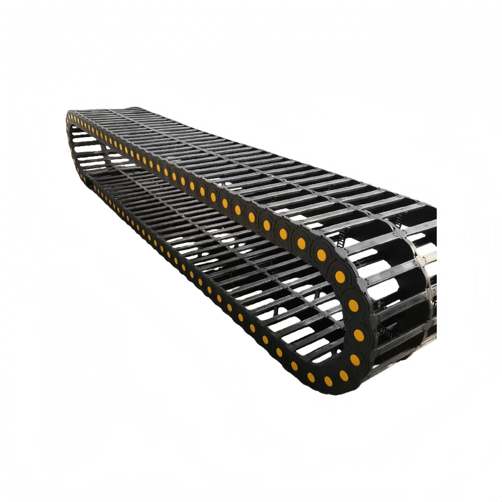
Engineering complex industrial machinery requires consistent precision across all subcomponents. QUNHUI manufactures dynamic flexible drag chain systems designed to meet demanding industrial standards. Our production facilities utilize high-purity, glass-fiber reinforced polymer formulations, providing balanced tensile stability, minimal hinge pin wear, and extended service life.
Whether you require open-style crossbar chains for high-speed pick-and-place automation, fully enclosed cable carriers resistant to hot tooling chips, or corrosion-resistant stainless assemblies, QUNHUI delivers modular configurations matched to your stroke, speed, and environmental requirements.
Frequently Asked Questions (FAQ)
What causes a dynamic cable to corkscrew inside a drag chain?
Corkscrewing happens when a cable twists axially inside the chain cavity. It is caused by three main factors: using cables not rated for continuous flexing, failing to unroll cables correctly from their spools during installation (which sets residual torsional stress), or lacking vertical separators to stop cables from rolling over one another.
Can I mix pneumatic hoses and electrical cables in the same drag chain?
Yes, provided you mechanically segregate them using vertical interior dividers or horizontal shelves. Pneumatic and hydraulic lines fluctuate in diameter when pressurized, which can compress and abrade neighboring electrical and signal lines if left unseparated.
How do I know whether my flexible drag chain needs an unsupported or gliding setup?
This is determined by the total payload (weight of all cables/hoses plus the chain itself per meter) compared against the manufacturer's unsupported length curve. If your travel stroke exceeds this curve, the upper run will sag onto the lower run. At that point, you must install an aligned guide trough with low-friction glide shoes.
Why are snap-open crossbars preferred over fully molded enclosed links?
Snap-open crossbars allow maintenance teams to install, repull, or inspect cables on-site without dismantling the entire machinery bracket or rewiring connector pins. Enclosed tube styles are reserved for applications that must be sealed against hot swarf, heavy dust, or falling debris.
What is the typical operational life of an engineered polymer drag chain?
When sized within its design parameters (staying below max ratings for acceleration, payload, bend radius, and fill ratio), a high-grade PA66 drag chain regularly achieves over 10 million dynamic cycles before requiring hinge pin or link replacement.
Request a Custom Engineering Review for Your Motion Setup
Prevent premature cable fatigue and avoid costly line stoppages. Contact the technical engineering team at QUNHUI today to review your application specifications. Send us your required stroke length, travel velocity, acceleration limits, and dynamic cable bundle diameters. Our design engineers will verify your layout, calculate exact minimum bending clearances, and deliver a configured CAD model and comprehensive quotation for your dynamic flexible drag chain system within 24 hours.