
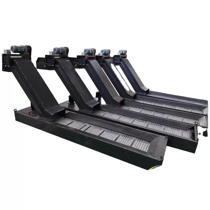
In high-volume manufacturing, the continuous removal of metal shavings, turnings, and swarf from the machining envelope is a primary factor in maintaining production continuity. High-speed CNC milling, turning, and multi-axis machining centers generate substantial volumes of scrap metal every hour. If left unmanaged, this debris accumulates inside the work envelope, leading to thermal distortion of the machine bed, damage to precision guideways, and premature wear on cutting tools. Integrating an efficient machine chip conveyor system addresses these challenges directly at the source, ensuring continuous operation and protecting capital equipment.
Industrial waste handling requires a systematic approach that balances machine tool geometry, material characteristics, and coolant flow rates. QUNHUI designs and manufactures heavy-duty chip evacuation systems engineered to meet the demands of modern automated factories. Selecting the correct machinery requires a detailed understanding of the mechanical forces, material interactions, and filtration methods that dictate conveyor performance.
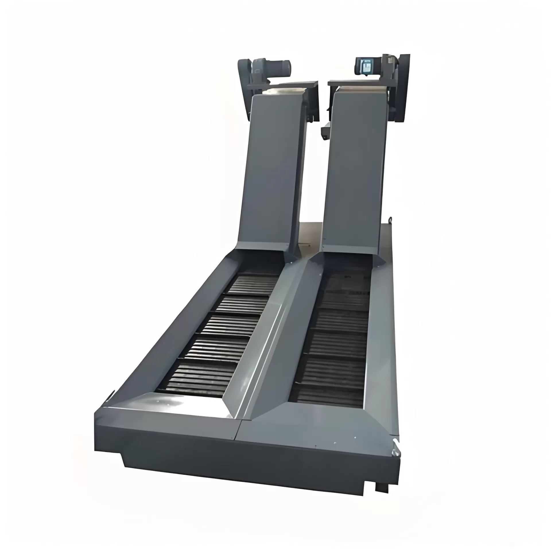
Categorizing Swarf Removal Technologies: Which Conveyor Suits Your
Operation?
Metal scrap is not uniform. The physical characteristics of the waste material—whether it consists of long, stringy steel turnings, fine cast iron dust, or light, high-volume aluminum chips—determine the mechanical design of the conveyor required. Implementing an incompatible system results in frequent mechanical jams, excessive coolant carryout, and increased maintenance downtime.
Hinged Belt Conveyors for Heavy and Stringy Scrap
The hinged belt design is the most widely utilized configuration in general machining. It features a continuous loop of steel aprons or plates linked together by heavy-duty roller chains. These plates often feature raised cleats or ribs that assist in elevating the material up the incline section of the frame.
Best Applied To: Long, curly, or bushy steel and brass turnings, heavy chunks, and drop-offs from turning centers.
Operating Mechanism: The belt moves over hardened wear tracks, carrying the scrap upward to the discharge chute. Closed-loop configurations prevent chips from entering the inner drive mechanism.
Limitations: Fine particles and micro-chips can pass through the gaps between the hinges, accumulating in the coolant tank over time.
Scraper and Drag Chain Systems for Fine and Broken Chips
For operations generating small, broken chips, such as those produced during the machining of cast iron, brass, or certain grades of aluminum, a scraper conveyor is more effective. Instead of a solid belt, this system utilizes dual-run chains connected by angled scraper bars (or drag flights).
Best Applied To: Small brass chips, cast iron granules, short aluminum chips, and fine steel swarf.
Operating Mechanism: The scraper bars drag along the machined bottom plate of the conveyor housing, pushing the accumulated sediment forward and up the incline.
Coolant Interaction: As the scraper moves the solids upward, coolant drains back down the incline through gravity, keeping the fluid within the machine reservoir.
Magnetic Conveyors for Ferrous Materials
When working exclusively with ferrous metals, such as carbon steels, alloy steels, and cast iron, magnetic separation offers a highly reliable alternative. This design eliminates moving external parts, reducing wear and mechanical failure.
Best Applied To: Fine steel chips, cast iron dust, and small ferrous components.
Operating Mechanism: High-intensity permanent magnets are attached to a chain drive running inside a sealed, oil-filled housing beneath a stationary stainless steel top plate. The external ferrous chips are attracted to the plate and slide along its surface, following the movement of the internal magnets until they reach the discharge zone.
Maintenance Profile: Because the moving drive components are completely sealed away from the abrasive chips and cutting fluid, component wear is minimal.
Analyzing the Interdependence of Coolant Filtration and Chip Evacuation
A machine chip conveyor does not operate in isolation; it is a key component of the CNC machine tool's coolant management system. During the cutting process, high-pressure coolant is delivered to the tool-workpiece interface to reduce friction and dissipate heat. This fluid washes the chips down into the conveyor hopper, meaning the conveyor must process both solid waste and high volumes of liquid simultaneously.
When chips are evacuated, they carry a film of cutting fluid on their surfaces. Inefficient chip separation leads to excessive coolant carryout, where valuable cutting fluid is dragged out of the machine and deposited into the scrap hopper. This depletes the coolant reservoir, increases chemical replacement costs, and creates environmental handling issues for the scrap metal. QUNHUI integrates specialized drainage zones, perforated screen plates, and optional coolant blow-off systems to maximize fluid retention within the machine tank.
Fine particles suspended in the coolant pose a threat to high-pressure pumps and internal spindle seals. If these particles bypass the primary machine chip conveyor, they recirculate through the coolant lines, causing abrasive wear on the tooling and deteriorating the surface finish of the machined parts. To prevent this, advanced conveyor designs incorporate secondary filtration elements, such as self-cleaning drum filters or integrated magnetic separators, which clean the coolant to a specific micron level before it returns to the main clean tank.
Key Engineering Parameters for Custom Integration
Standard off-the-shelf conveyors rarely meet the spatial and operational demands of specialized production lines. When specifying a custom machine chip conveyor with QUNHUI, several mechanical and spatial parameters must be calculated to ensure seamless integration with the CNC machine tool.
| Parameter | Engineering Considerations | Impact on Performance |
|---|---|---|
| Incline Angle | Typically ranges from 30°, 45°, to 60° based on floor space and discharge height requirements. | Steeper angles reduce the horizontal footprint but increase the potential for chips to slide backward, requiring taller cleats. |
| Belt Width & Pitch | Standard pitches include 31.75mm (1.25"), 38.1mm (1.5"), and 50.8mm (2.0"). | Determines the volumetric capacity of the conveyor. Larger pitches handle higher scrap volumes without clogging. |
| Discharge Height | Must clear the rim of standard industrial chip hoppers or central collection carts. | Incorrect height leads to chip accumulation at the exit nozzle, causing mechanical lockups. |
| Drive Motor & Safety Clutch | Variable speed gear motors paired with mechanical torque limiters or electronic overload sensors. | Protects the conveyor frame and drive chain from structural damage if a foreign object falls into the hopper. |
Material selection for the conveyor wear surfaces is another critical factor. Abrasive materials like cast iron, silicon-aluminum alloys, and hardened steels rapidly erode standard mild steel frames. Specifying manganese steel wear plates or hardened guide tracks along the high-wear zones of the conveyor path significantly extends the operational lifespan of the equipment.
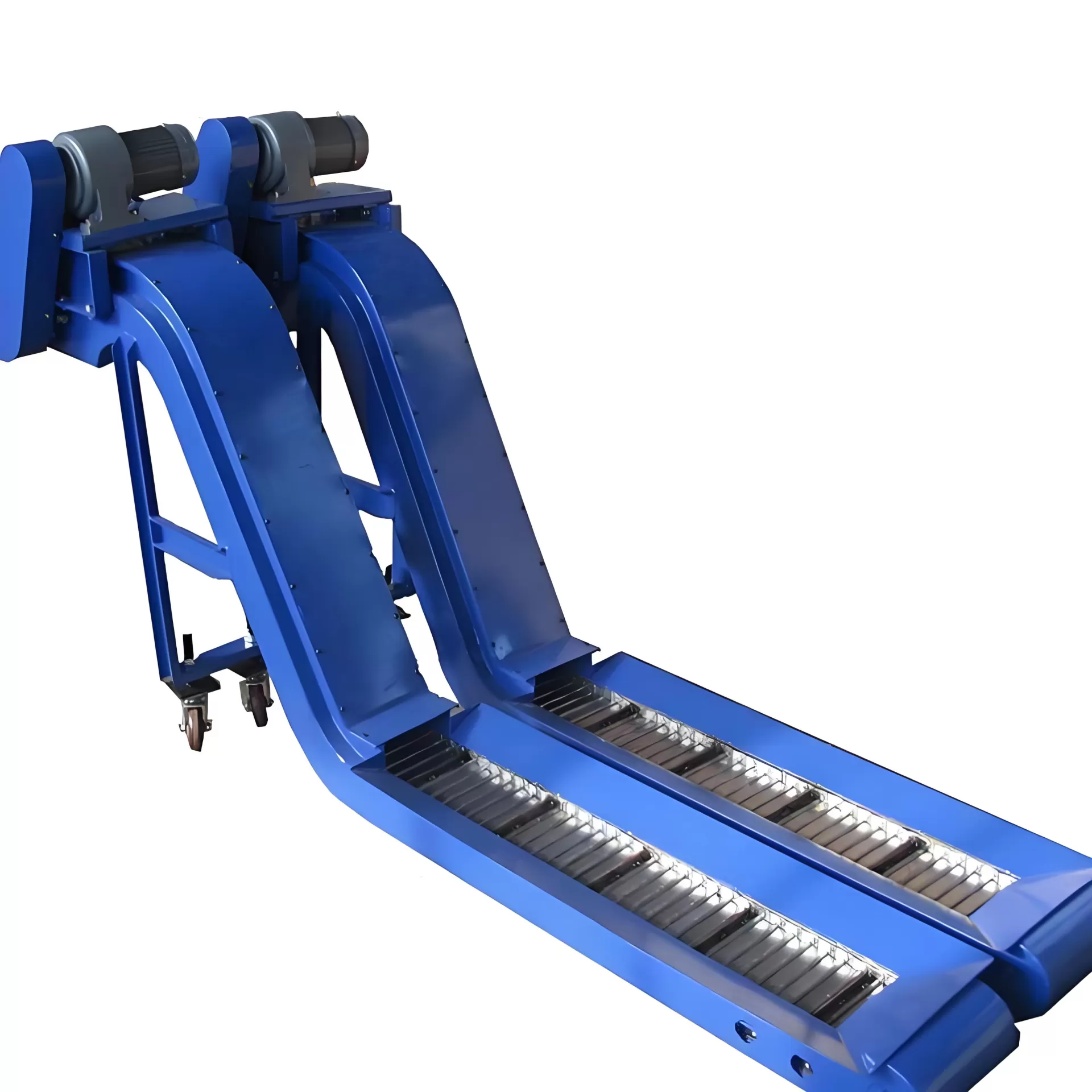
Addressing Operational Challenges in Scrap Handling
Industrial environments present harsh operating conditions that test the durability of material handling systems. A common issue is chip nesting, where long, continuous steel turnings entangle and form large, bird-nest-like structures. These nests can bridge across the conveyor inlet, preventing subsequent chips from entering the belt and eventually causing a complete blockage of the machine enclosure.
To mitigate chip nesting, CNC programs can be written to utilize chip-breaking cycles, but the mechanical design of the conveyor hopper must also assist in breaking up these clusters. QUNHUI incorporates specialized hopper geometry and optional pre-shredding or macerating units at the conveyor inlet to reduce large nests into manageable pieces before they reach the conveyor belt.
Conveyor jamming due to part drop-offs or broken tooling is another frequent cause of unscheduled downtime. When a heavy piece of bar stock or a broken solid carbide end mill falls into the conveyor, it can wedge between the moving belt and the steel frame. Without safety mechanisms, the drive motor will continue to pull, bending the steel slats, snapping the drive chain, or burning out the motor winding. Implementing a mechanical slip clutch or an electronic current-monitoring auto-reverse cycle allows the system to detect the obstruction, stop immediately, and attempt to back out the jam automatically before alerting the operator.
FAQs
Q1: What are the main indicators that a machine chip conveyor belt needs tensioning?
A1: Visible sagging of the belt in the lower return section, unusual clicking or popping noises from the drive sprockets, and uneven tracking of the belt along the internal guide rails indicate that the tension requires adjustment. Regular inspection of the take-up bolts on either side of the discharge frame is recommended to maintain correct tension and prevent chain derailment.
Q2: How does the type of cutting fluid affect the selection of conveyor materials?
A2: Water-soluble coolants, synthetic fluids, and neat cutting oils react differently with conveyor components. Water-based coolants require rust-resistant coatings, high-grade seals, and proper drainage paths to prevent corrosion of the roller chains. Neat oils possess higher viscosity, which can cause fine chips to adhere to the conveyor frame, requiring specialized scraper wipers to clean the belt surface.
Q3: Can a scraper conveyor be converted to handle long steel turnings?
A3: Generally, no. Scraper conveyors are designed specifically for short, broken chips. Long, stringy turnings will wrap around the scraper bars and the drive chains, causing rapid mechanical binding and potential structural damage to the system. For mixed chip profiles, a hinged steel belt conveyor is the standard recommendation.
Q4: What maintenance steps are required to prevent fine particles from settling in the coolant tank?
A4: While the primary conveyor removes larger chips, fine particles must be addressed through continuous filtration. Operators should regularly clean the chip basket at the conveyor return, inspect the internal wear plates for gaps, and ensure that the coolant tank's baffle plates are free of sludge accumulation. Implementing an auxiliary paper band filter or cyclonic separator is highly effective for fine particulate management.
Q5: Why is aluminum chip removal more challenging than steel chip removal?
A5: Aluminum chips are extremely lightweight and tend to float on the surface of the coolant rather than settling onto the conveyor belt. Additionally, aluminum is highly ductile and can stick to the metal surfaces of the conveyor frame under pressure. Conveyors designed for aluminum require specialized steep incline angles, coolant flush lines to push the floating chips onto the belt, and non-stick material coatings.
Contact Our Engineering Team for Custom Specifications
Every manufacturing facility maintains a unique set of production requirements, spatial constraints, and material workflows. QUNHUI engineers custom-engineered chip evacuation and filtration systems designed to interface with your existing CNC machinery and factory automation layouts. To discuss your project specifications, obtain detailed technical drawings, or request a quotation for a dedicated machine chip conveyor system, please submit an inquiry to our technical sales team.