
-(3).webp)
Modern metalworking and high-production CNC machining operations generate substantial volumes of scrap metal material. Efficient removal of these metal turnings, chips, and borings is necessary to maintain continuous production cycles, protect high-precision workpieces, and prevent mechanical interference within the machine envelope. At the center of these removal systems is the chip conveyor chain, a mechanical component responsible for pulling heavy abrasive materials out of the coolant tank and delivering them to collection receptacles.
Selecting the appropriate configuration for this mechanical link requires a thorough understanding of mechanical stress, material wear characteristics, and the physical properties of the scrap being transported. An incorrect selection can result in frequent machine stoppages, high maintenance costs, and premature wear of the entire conveyor assembly. This detailed analysis examines the structural engineering of these assemblies, compares different design variations, and details key maintenance strategies for industrial operations.
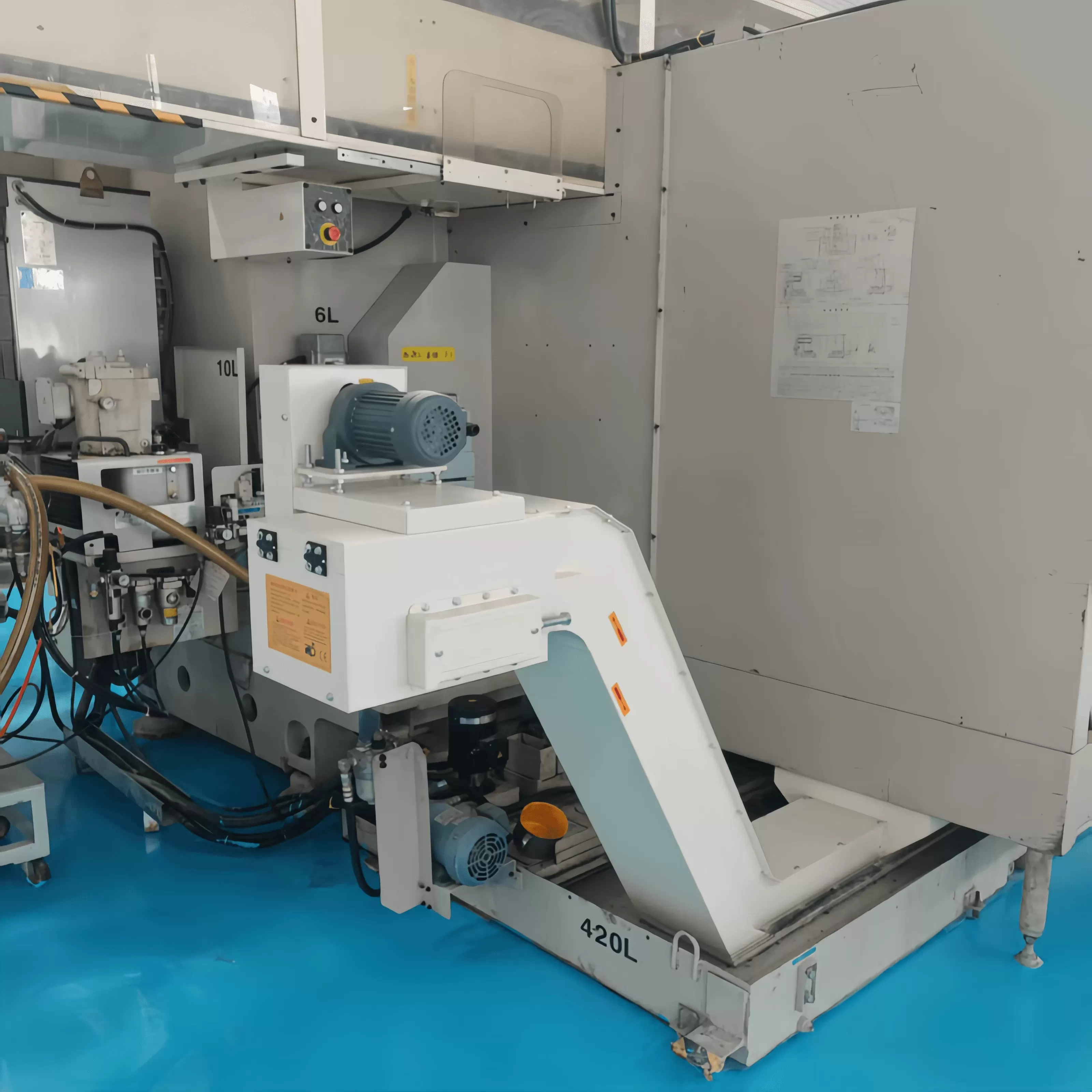
Structural Anatomy of a Chip Conveyor Chain
To evaluate how these components perform under continuous load, we must first analyze their structural components. Unlike standard transmission chains, these specialized conveyor links must withstand both high tensile pull and constant abrasive wear from sharp, hardened metal fragments.
Apron Plates (Belt Plates): These overlapping plates form the continuous surface that carries the scrap. They are typically pressed from carbon steel or stainless steel. The design of these plates must prevent fine particles from passing through the joints into the internal track.
Side Links and Roller Links: These elements bear the primary tensile forces exerted by the drive sprockets. They are precision-stamped to ensure uniform pitch spacing, which prevents jerky movement and reduces vibration.
Hardened Connecting Pins: Serving as the pivot points, these pins are subjected to high shear stresses. They undergo specialized heat treatment to achieve high surface hardness while maintaining a ductile core to absorb sudden shock loads.
Side Wings (Flanges): These vertical plates are welded or integrated into the sides of the belt plates. They create a moving barrier that prevents long, stringy turnings from wrapping around the stationary conveyor frame or entering the drive mechanism.
Each of these components must work in harmony. If the manufacturing tolerances are too loose, fine particles will find their way into the pin-and-bushing clearance zone, accelerating abrasive wear and causing premature pitch elongation.
Mechanical Classifications and Application Suitability
Industrial manufacturing environments generate distinct profiles of scrap material. Consequently, conveyor designs are divided into several operational classes, each matching a specific type of metal debris.
Hinged Steel Belt Systems
This design is widely used in general milling, turning, and machining centers. The hinged plate configuration forms a closed surface that easily transports heavy, curly steel turnings, wet chips, and sharp scrap pieces. The interlocking hinge design provides high structural rigidity, allowing it to withstand the direct impact of heavy parts dropping from the machine spindle during setup or part ejection. This style is highly effective for ferrous and non-ferrous metals alike, provided the chips are larger than the minimum clearance between the hinge loops.
Scraper and Drag Conveyor Systems
When machining cast iron, brass, or bronze, the process produces very fine, powdery chips that tend to settle quickly at the bottom of the coolant tank. Hinged belts struggle with these fine particles because they can pass through the plate joints. Scraper systems address this issue by using flight bars mounted between parallel strands of chain. These bars drag along the machined steel bottom of the conveyor trough, scraping the settled fines up the incline. This ensures that the coolant tank remains clear of sediment accumulation, which is key for maintaining fluid quality and preventing pump damage.
Magnetic Conveyor Systems
For operations exclusively processing ferrous metals, magnetic systems offer a robust alternative. In this design, the moving components remain fully enclosed beneath a stationary stainless steel plate. Magnets attached to the internal moving chain attract the iron or steel chips through the plate, sliding them along the surface to the discharge chute. Because the moving parts are never in direct contact with the abrasive metal debris, this design experiences significantly less wear and virtually eliminates the risk of jamming from trapped parts.
Primary Mechanisms of Chain Wear and Degradation
Understanding why these systems fail is key to choosing the right specifications for replacement components. In wet machining environments where corrosive coolants and highly abrasive metals are present, several degradation mechanisms act simultaneously.
A major source of degradation is pitch elongation, often referred to as stretching. This phenomenon is not caused by the actual stretching of the steel plates, but rather by the wearing away of material on the outer surface of the pins and the inner bore of the bushings. As the clearance between these parts increases, the cumulative length of the loop grows. This elongation leads to a mismatch with the drive sprocket teeth, resulting in chain jumping, tooth wear, and localized mechanical shocks that can break the links.
Another common issue is side plate wear. When a conveyor system is misaligned or experiences uneven tension, the side plates rub directly against the internal steel guides of the frame. This constant friction thins the structural plates, reducing their maximum tensile strength. If left unaddressed, the weakened plates will yield under the high starting torque of the drive motor, causing a complete system break.
Additionally, the chemical composition of the cutting fluid plays a major role in component longevity. Water-soluble coolants can cause localized oxidation if the pH level is not properly monitored. When combined with mechanical abrasion, this chemical action creates a cycle of stress corrosion cracking, which can cause sudden, brittle failure in hardened carbon steel links.
Key Selection Parameters for Engineering Specifications
When selecting a replacement or custom chip conveyor chain for an industrial facility, engineers must evaluate several parameters to match the system to the operational environment.
Pitch Selection: Standard pitch dimensions generally range from 31.75mm (1.25 inches) for light-duty, compact CNC machines, up to 101.6mm (4.0 inches) or more for heavy-duty automotive scrap lines. A larger pitch allows for heavier plate construction and larger pin diameters, increasing overall tensile load capacity.
Material Grades: For standard operations, high-tensile carbon steels with induction-hardened wear parts are sufficient. However, for corrosive environments or operations machining highly abrasive materials like titanium or silicon-aluminum alloys, stainless steel or specialized alloy coatings are recommended to prolong service life.
Roller Configuration: Flanged rollers help guide the path through the conveyor frame, reducing lateral movement and wear on the side links. Plain rollers are suitable for straight, short runs where lateral forces are minimal.
Tensioning Mechanisms: Incorporating reliable take-up units, such as spring-loaded or mechanical screw adjusters, helps maintain the correct tension as the components break in, preventing slack that could lead to sprocket derailment.
.webp?t=1784542875158 "螺旋式排屑机-(8)")
QUNHUI Solutions for Industrial Environments
Addressing these complex wear mechanisms requires high manufacturing precision and specialized material treatments. QUNHUI designs and manufactures high-performance conveyor components designed to meet the rigorous demands of continuous industrial production.
By utilizing controlled induction hardening for pins and bushings, QUNHUI ensures that the components resist abrasive wear while retaining the core ductility needed to withstand sudden mechanical jams. Our manufacturing processes enforce tight tolerances on plate hole alignment and pin diameters, which minimizes the entry of abrasive fine particles into the pivot joints. This design focus significantly reduces pitch elongation, ensuring smooth engagement with drive sprockets over a longer operating life.
Whether you are managing a high-volume automotive manufacturing line or operating custom CNC machining cells, QUNHUI provides engineered solutions tailored to your specific scrap profile and machine tool dimensions, helping to minimize unplanned downtime and lower overall maintenance costs.
Frequently Asked Questions
Q1: How can I identify when my chip conveyor chain is nearing the end of its useful life?
A1: The most reliable indicators are pitch elongation and sprocket mismatch. If the chain frequently jumps on the drive sprockets, or if the manual tensioning adjustment has reached its limit, the joint clearances have likely worn beyond acceptable tolerances. Visually inspect the side plates for deep wear grooves and check the pins for flat spots, which indicate a need for replacement.
Q2: What is the impact of incorrect chain tension on the conveyor system?
A2: Excessively tight tension increases the mechanical load on the pins, bushings, and drive motor bearings, accelerating wear and increasing the risk of sudden breakage. Conversely, loose tension allows the chain to bunch up at the bottom turn, leading to binding, sprocket jumping, and potential jamming against the internal frame guides.
Q3: How do dimpled apron plates compare to flat plates in sticky chip applications?
A3: Flat plates are suitable for dry, non-sticky chips. However, when machining materials with heavy cutting oils, the surface tension of the fluid can cause the chips to adhere to flat plates, preventing proper discharge at the chute. Dimpled plates feature a textured surface that breaks this surface tension, allowing sticky, oil-covered chips to drop off easily into the collection bin.
Q4: Can a standard steel chain be used in high-acid or water-soluble coolant systems?
A4: While standard carbon steel can be used if the coolant has excellent rust-inhibiting properties and is kept at the proper concentration, water-soluble coolants with low concentration levels can accelerate rust and stress corrosion. In such environments, using specialized coatings or stainless steel links is highly recommended to prevent premature material failure.
Q5: What steps should be taken to prevent long, stringy aluminum chips from jamming the system?
A5: Stringy aluminum chips have a high volume-to-weight ratio and easily wrap around moving parts. To handle this material, use a hinged belt with extra-tall, overlapping side wings to keep the chips contained on the carrying surface. Ensure the conveyor speed is set correctly to prevent a large mass of chips from accumulating in the lower curve of the conveyor housing.
Connect with Our Engineering Team
Selecting the right mechanical components for your chip evacuation system is key to maintaining consistent production and reducing unexpected maintenance overhead. Our team at QUNHUI has the engineering experience required to analyze your specific machining parameters, chip characteristics, and equipment configurations to recommend the most reliable solution.
For custom manufacturing inquiries, detailed specification sheets, or direct quotes on replacement assemblies, please contact our sales and engineering support department. We are ready to assist you in finding a durable solution for your operation.