
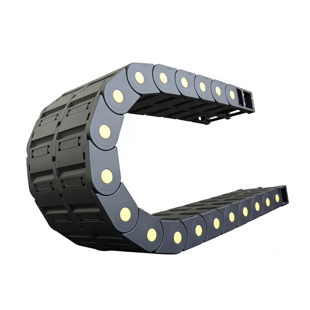
Automated manufacturing systems and multi-axis CNC machine tools require reliable energy and signal transmission across high-cycle linear paths. Cable carrier assemblies serve as the primary protective conduit for power cables, feedback lines, pneumatic hoses, and hydraulic runs. Selecting an engineered polymer carrier requires a complete evaluation of structural mechanics, material tribology, acceleration rates, and environmental conditions to avoid line failure and unplanned production halts.
Material Properties and Polymer Mechanics
Modern non-metallic energy conduits rely on modified polyamides, primarily Polyamide 66 (PA66) reinforced with targeted percentages of surface-treated glass fibers, typically ranging between 15% and 35% by weight. Unreinforced standard polymers lack the dimensional stability and modulus of elasticity needed to sustain high unsupported spans under dynamic load. The inclusion of glass fibers enhances yield strength, flexural modulus, and continuous operating thermal resistance while retaining impact toughness during high-frequency reversal cycles.
A high-performance nylon drag chain exhibits specific mechanical behaviors across standard operating environments:
Tensile Modulus: Reinforced PA66 formulations deliver a tensile modulus between 5,000 MPa and 9,500 MPa at 23°C and 50% relative humidity, preventing lateral sag across wide dynamic strokes.
Thermal Range: Continuous performance spans from -40°C to +130°C, with short-term thermal resistance handling localized friction points up to +180°C.
Dynamic Friction Coefficient: Unlubricated polymer-on-polymer sliding interfaces maintain a friction coefficient between 0.22 and 0.28, reducing motor drive torque requirements in gliding configurations.
Dielectric Properties: High volume resistivity (exceeding 1012 Ω·cm) isolates electrical feedback lines from surrounding static charges.
Polymer matrix compounding dictates how the carrier handles micro-notching and abrasive environmental particles. In machining centers where hot metallic swarf and synthetic coolant mists are continuous, raw PA66 is stabilized against chemical hydrolysis and ultraviolet degradation. Chemical stabilizers prevent moisture-induced plasticization from lowering yield strength, ensuring the carrier maintains its structural rigidity throughout millions of directional changes.
Unsupported Length Calculations and Dynamic Kinematics
The operational geometry of an energy carrier depends on the unsupported span ($L_{FL}$), which represents the maximum distance the upper run travels above the lower run without sagging onto lower surfaces or bending upward beyond allowable tolerances. Exceeding this mechanical threshold leads to premature material fatigue and mechanical link breakdown.
Calculation of the required carrier loop length ($L_k$) utilizes the stroke length ($S$), selected bend radius ($R$), and chain link pitch ($T$):
$$L_k = \frac{S}{2} + (\pi \cdot R) + (2 \cdot T)$$
Engineers evaluate the total fill weight ($q_k$, expressed in kg/m), which includes the aggregate mass of all electrical conductors, fluid hoses, and internal separator components. Structural finite element models developed by manufacturers like QUNHUI calculate the operational boundary between the unsupported straight condition ($L_{FLG}$) and the unsupported sagging condition ($L_{FLB}$).
When the installation demands acceleration rates exceeding 10 m/s² or velocities beyond 5 m/s, inertia introduces severe shock loads at the reversal points. During rapid deceleration, dynamic bending moments concentrate directly on the chain link pin-and-bore pivot joints. The cross-sectional shear area of the hinge pin must absorb these peak forces without permanent plastic deformation. A nylon drag chain engineered with dual-shear pin designs provides double the load distribution area compared to single-lug designs, raising dynamic limits and operational service life.
Internal Compartmentalization and Conduit Distribution
Cables and hoses placed within a moving energy conduit undergo complex shear, tensile, and compressive strains. Improper line distribution inside the cavity causes conductors to twist into corkscrews, resulting in core-wire breakage and hydraulic outer-jacket abrasion.
Cable longevity requires strict adherence to spatial clearance and partitioning rules:
Clearance Margins: Maintain an internal diameter clearance of at least 10% to 15% for electrical cables and 20% for pneumatic/hydraulic hoses relative to their respective cavity compartments.
Neutral Axis Alignment: Heavy hydraulic conduits must sit symmetrically along the centerline to prevent asymmetric moments that force the carrier to twist along its longitudinal axis.
Vertical and Horizontal Separation: Cables of widely differing outer diameters must not cross over one another. Use modular polymer separators and horizontal shelving to isolate each conductor into a distinct chamber.
Strain Relief Protocols: Secure all conductors using profile-matched strain relief clamps at both the moving tow-arm bracket and the fixed base point. Secure lines at the neutral line without crushing the insulation or restricting fluid flow.
In high-speed linear motor axes, unequal mass distribution generates secondary vibrations that compromise machining surface finishes. Symmetrical compartmentalization keeps the center of gravity stable, minimizing harmonic oscillation across the structural machine frame.
Design Configurations: Open Frame vs. Fully Enclosed Tubes
Selecting between an open-frame crossbar design and an enclosed tube depends entirely on the ambient operating environment and particulate exposure profile.
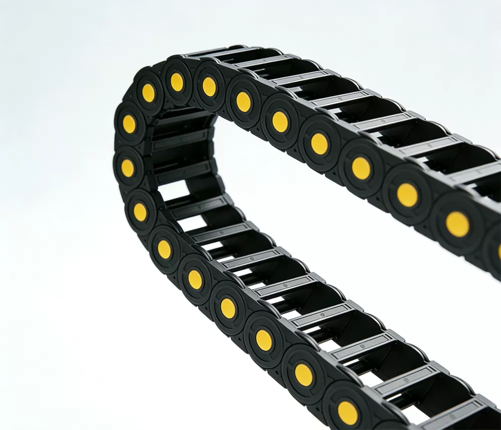
Open-frame designs incorporate hinged, snap-open crossbars on both the internal and external radii. These units maximize airflow around high-power servomotor cables, facilitating heat dissipation during continuous high-amperage cycles. Open crossbars also permit fast visual inspection and rapid cable installation without dismantling machine enclosures.
Fully enclosed polymer tubes provide continuous barrier protection across all axes. In heavy-duty milling, routing, and grinding machinery, fine cast-iron dust, continuous coolant streams, and high-velocity metal chips bombard the carrier. An enclosed nylon drag chain shields inner flexible lines from hot chip impingement, preventing jacket melting, short circuits, and hydraulic degradation. Precision-molded seal lips along the interlocking joints maintain chip exclusion without adding excessive joint friction during high-speed articulation.
Gliding and Long-Travel System Implementation
When continuous linear travel exceeds the unsupported limit—typically past 4 to 6 meters depending on fill mass—the carrier must operate in a gliding configuration where the upper run rides directly on top of the lower run inside a dedicated guide trough.
Long-travel installations introduce specific physical dynamics:
Guide Troughs: Channel sidewalls must maintain exact parallel alignment within a ±2 mm tolerance across the entire axis length to avoid lateral side-load stresses on the link plates.
Glide Shoes: Replaceable low-friction polymer glide shoes attached to the link sides lower frictional wear, functioning as sacrificial components that protect the load-bearing side links.
Reverse Bend Radius (RBR): Multi-axis designs and opposing-carrier arrangements use reverse bend configurations to manage complex nested travel envelopes within compact CNC footprints.
QUNHUI integrates specialized low-wear polymer blends into glide-shoe interfaces to lower static breakaway friction and suppress slip-stick behavior during slow, precise feed sequences. This material synergy cuts parasitic drive load while stabilizing velocity profiles across multi-meter travel paths.
Tribology, Wear Factors, and Structural Diagnostics
The operational lifespan of a composite polymer carrier is governed by the mechanical wear of its articulating hinges. The cyclical rotation of the pin within the mating bore generates frictional heat and micro-particulate shedding.
Hinge wear rates are a function of contact pressure ($P$), relative rotational velocity ($V$), and the polymer wear factor ($K$):
$$W = K \cdot P \cdot V \cdot t$$
As the pin and bore wear down, the carrier experiences pitch elongation. This physical change alters the designed bend radius and causes the upper run to sag below nominal limits. If uncorrected, this change can cause the carrier to collide with stationary machinery or guide trough boundaries.
Diagnostic inspections must monitor hinge joint clearance, lateral play, and stop-dog integrity. The mechanical stop-dogs integrate into each link to define the precise bend radius and lock the carrier rigid in its unsupported run. Impact fatigue can crack or deform overloaded stop-dogs. Using multi-axis vibration analysis and acoustic emission sensors allows predictive maintenance teams to detect joint wear and plan carrier replacement before line failures interrupt operations.
Comparative Mechanical Metrics
Evaluating energy carrier constructions requires comparing primary physical indicators across typical operational profiles:
Reinforced Nylon (PA66-GF): Density of 1.35–1.45 g/cm³, maximum acceleration up to 50 m/s², low operational noise (below 45 dB(A)), excellent resistance to shop chemicals and coolants, zero maintenance lubrication required.
Galvanized or Stainless Steel: Density of 7.85 g/cm³, maximum acceleration limited to 5 m/s², higher acoustic emission (above 70 dB(A)), superior structural load capacity across long self-supporting spans, regular pivot pin lubrication required.
Hybrid (Steel Chains with Polymer Bridges): Balanced load capacity for heavy hydraulic hoses, moderate acceleration (up to 15 m/s²), moderate acoustic output, periodic mechanical joint inspection required.
For high-speed CNC machinery, robotic gantries, and automated pick-and-place systems, an engineered nylon drag chain represents the ideal balance of low moving mass, high dynamic acceleration capacity, and lubrication-free operation.
Frequently Asked Questions
What determines the proper bend radius for a dynamic cable carrier?
The bend radius is dictated by the thickest or least flexible cable or hose installed in the bundle. As a standard rule, dynamic electrical cables require a minimum bend radius of 7.5 to 10 times their outer diameter, while dynamic hydraulic hoses require 10 to 12 times their outer diameter. Selecting a carrier bend radius smaller than the largest cable recommendation leads to inner conductor fatigue and premature jacket wear.
How do dynamic loads affect the choice between open and closed carriers?
Open carriers offer reduced moving mass, which benefits high-acceleration and high-velocity applications by decreasing motor inertia and heat buildup. Fully enclosed carriers add mass and capture internal thermal energy from high-cycle power cables, but they provide mandatory physical defense against hot metal swarf, abrasive grit, and continuous chemical splash in harsh cutting environments.
Why is neutral axis separation necessary within the chain cavity?
As the carrier flexes through the bend radius, lines positioned above the neutral axis experience dynamic tension, while lines positioned below it undergo compression. Isolating conduits into dedicated chambers with interior vertical separators and horizontal shelves prevents cables from rubbing, entangling, or exerting uneven lateral forces on the carrier walls.
Can a nylon drag chain operate in long-travel horizontal applications?
Yes, by utilizing an engineered guide trough system and configuring the carrier for gliding operation. When the travel distance exceeds the unsupported limit, the upper run glides smoothly over the lower run. In these extended setups, incorporating low-friction glide shoes and ensuring trough alignment within strict parallel tolerances prevents side-plate deflection and extends system longevity.
How does ambient chemical exposure influence carrier polymer selection?
Synthetic machine coolants, oils, acids, and atmospheric moisture can interact with standard polymers, inducing swelling, plasticization, or micro-cracking. Specifying PA66 with specialized chemical stabilizers preserves yield strength, impact resistance, and dynamic flexural life under continuous exposure to cutting fluids and industrial solvents.
What are the primary indicators that a carrier has reached end-of-life?
Key indicators include excessive sag in the upper unsupported run caused by stop-dog fatigue, increased lateral deflection during travel, noticeable link hinge thinning from abrasive pin wear, micro-cracking near the pivot bores, and increased mechanical drive resistance on the machine axis motor.
Select the Right Cable Carrier Solution
Precision-engineered machine designs require matching motion components to real-world mechanical loads. The engineering team at QUNHUI configures high-durability carrier assemblies tailored to exact dynamic parameters, stroke lengths, and environmental demands. Contact our application engineers today to discuss your machinery specifications, request comprehensive dimensional drawings, and secure quotes for your automated motion systems.