
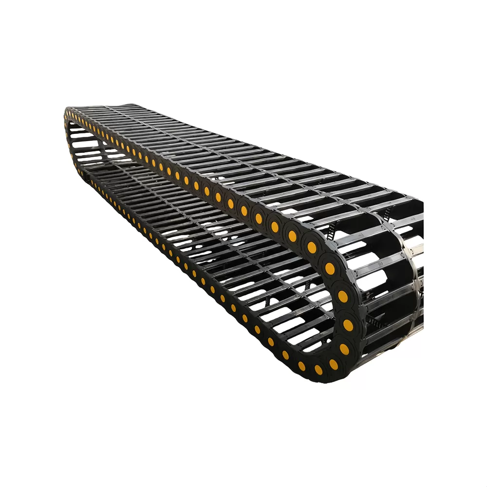
Automated manufacturing environments subject power feeds, hydraulic lines, and data conduits to severe continuous acceleration and abrasive conditions. In high-speed multi-axis CNC machine centers, automated gantries, and industrial robotic cells, internal routing must maintain structural integrity across millions of continuous flex cycles. Integrating a reinforced nylon cable drag chain provides the mechanical stability and spatial management needed to guide moving conductors without inducing localized stress concentrations, cable entanglements, or premature core fatigue.
Industrial machinery builders require energy supply systems capable of balancing structural stiffness with lightweight flexibility. Engineered polymers, specifically high-grade polyamides, have largely superseded traditional sheet steel in light-to-medium dynamic applications due to their high strength-to-weight ratios, self-lubricating qualities, and chemical neutrality against machining coolants and industrial lubricants.
Material Composition and Polymer Dynamics
The foundation of long-term track reliability resides in polymer material science. Standard plastics degrade under constant cyclic tension, thermal variances, and hydrocarbon exposure. Heavy industrial tracks utilize polyamide 66 (PA66) heavily modified with glass fiber reinforcement, typically ranging from 15% to 35% by volume.
The integration of micro-glass fibers increases the tensile modulus, limits creep under continuous load, and raises heat deflection thresholds. Unmodified nylon exhibits hygroscopic tendencies, absorbing ambient moisture which alters its dimensional stability and flexural modulus. PA66-GF composites engineered by manufacturers such as QUNHUI maintain tight dimensional tolerances and mechanical damping properties across wide temperature spectrums, typically from -40°C to +130°C.
Tensile Strength at Yield: High-grade modified PA66 delivers yield strengths exceeding 150 to 180 MPa, resisting tensile rupture during rapid axis acceleration.
Impact and Abrasion Resistance: Glass-reinforced matrices protect against surface gouging caused by flying metal chips, composite dust, and abrasive particulate matter.
Dynamic Friction Coefficient: Self-lubricating polymer additives minimize friction at the link pivot pins, reducing operational noise, internal wear, and particle shedding in clean manufacturing environments.
Chemical Resistance: Inertness against synthetic coolants, cutting oils, dielectric fluids, and common industrial solvents prevents structural softening or embrittlement over multi-year duty cycles.
Kinematic Parameters and Structural Sizing Calculations
Specifying the proper nylon cable drag chain requires precise mathematical verification of dynamic physical forces, mechanical dimensions, and machine travel limits. Arbitrary sizing frequently leads to unsupported chain sag, pin shear, or cable sheath rupture.
1. Calculation of Total Chain Length
For horizontal setups where the fixed end is positioned in the center of travel, the nominal chain length ($L_k$) is determined using the machine stroke distance ($S$) and the chosen bending radius ($R$):
Formula: $L_k = \frac{S}{2} + (\pi \times R) + (2 \times P)$
Where $P$ represents the individual chain pitch. When the fixed end is offset from the center of travel, the differential travel distance must be added directly to the total length calculation to prevent dynamic tension at full axis extension.
2. Determining Minimum Bending Radius
The bending radius ($R$) of the assembly is governed exclusively by the thickest or stiffest conduit housed within the cavity. Exceeding recommended minimum bending radii induces internal conductor strand shearing and premature jacket hardening.
Electrical Power and Control Cables: The carrier bend radius should be at least $7.5\times$ to $10\times$ the outer cable diameter ($d$).
Dynamic Data and Optical Fiber Lines: Require an internal bend radius of $10\times$ to $12.5\times$ outer cable diameter.
Hydraulic and Pneumatic Hoses: Must maintain an operational bend radius of $10\times$ to $12\times$ hose outer diameter to avoid bore restriction and wall fatigue under internal fluid pressurization.
3. Unsupported Length and Dynamic Load Limits
The unsupported length ($F_L$) refers to the distance the upper run of the carrier can travel horizontally without touching the lower run. This metric is divided into two operational zones: straight unsupported travel ($F_{Ls}$) where the chain displays zero deflection, and sagged unsupported travel ($F_{La}$) where a measurable downward curve occurs without compromising structural stability.
Exceeding the maximum unsupported length threshold forces the upper run to collapse onto the lower run, creating excessive friction, abrasive wear, and accelerated pin destruction at higher velocities. When travel distances exceed the unsupported limit (often beyond 4 to 6 meters depending on fill weight), guide troughs and continuous glide shoes must be installed to support the returning run.
Structural Variations: Open Frame versus Fully Enclosed Enclosures
Machine design parameters dictate whether an open crossbar frame or a fully sealed conduit configuration provides superior long-term performance.
Open Frame (Bridge Type) Configurations
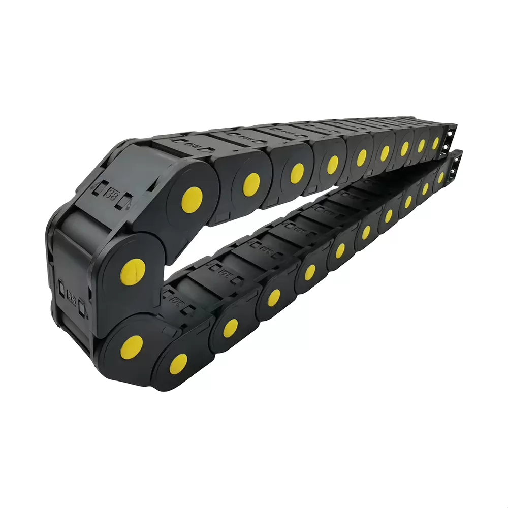
Open-frame carriers utilize snap-open crossbars on either the inner or outer radius. This open architecture facilitates continuous thermal dissipation, preventing heat accumulation generated by high-current power cables and high-pressure hydraulic lines. In addition, open structures simplify visual inspections, reduce total moving mass on high-speed linear motors, and allow rapid cable retrofitting without dismantling the complete chain track.
Fully Enclosed Polymer Tubes
Machining environments producing continuous streams of hot chips, casting scale, fine abrasive grit, or weld spatter require fully enclosed polymer tube designs. Enclosed interlocking lids create an impenetrable barrier that keeps destructive debris away from delicate dynamic cables. High-performance enclosed designs utilize labyrinthine lid joints that block particulates while maintaining smooth rotational movement across every link segment.
Conduit Layout and Cavity Interior Separation Protocols
Uncontrolled internal cable movement is a major contributor to premature system breakdown. Inside a moving carrier, cables and hoses naturally attempt to twist and migrate across the cavity, creating friction knots, jacket abrasion, and core failure.
Engineers must implement strict clearance protocols to guarantee free dynamic movement within the internal cross-section:
Clearance Margins: Always maintain a minimum 10% to 15% radial clearance (or at least 1.5 to 2 mm) between the outer surface of any cable and the adjacent partition wall or crossbar.
Mass Balancing: Distribute weight symmetrically across the chain width. Heavier power conduits and steel-braided hydraulic hoses must be secured symmetrically near the outer link plates, while lightweight sensor cables reside in the central zone. This symmetrical distribution neutralizes lateral moment forces and avoids uneven wear on track pivot pins.
Vertical and Horizontal Partitioning: Conduits of disparate outer diameters or different jacket materials (such as PUR, PVC, and rubber) must never be stacked loosely on top of one another. Rigid vertical separators and horizontal shelving must segregate every line into dedicated chambers, permitting individual axial expansion during continuous flexing.
Neutral Axis Positioning: Clamping must secure cables firmly at both the moving drive bracket and the fixed mounting bracket using strain relief combs. Conduits must float freely within the neutral axis of the chain loop, neither stretched tightly against the inner bend radius nor crushed outwards against the outer crossbar.
High-Duty Industrial Machine Applications
Modern CNC machine tools and material handling systems impose unique mechanical challenges that require targeted cable carrier configurations.
Five-Axis CNC Machining Centers
In high-speed 5-axis vertical machining systems, feed rates can exceed 60 m/min with accelerations surpassing 1.5g. Dynamic forces place tremendous inertial stress on every link segment. Utilizing an engineered nylon cable drag chain dampens structural vibrations and resists link elongation caused by instantaneous acceleration spikes, ensuring repeatable axis positioning without cable-induced drag.
Heavy Gantry Laser and Plasma Cutting Systems
Laser and thermal cutting gantries combine long travel strokes (often reaching 15 to 30 meters) with fine particulate contamination. High-performance energy supply systems manufactured by QUNHUI incorporate reinforced pivot structures and low-wear polymer glide shoes, enabling smooth gliding movement over extended travel distances without structural derailment or excessive friction drag.
Automated Stamping and Press Transfer Units
Automated transfer presses generate intense mechanical shock loads and severe low-frequency vibrations with every machine cycle. Standard mechanical tracks can loosen or crack at the hinge points under these conditions. Specially formulated impact-modified PA66 materials maintain link integrity, absorbing high shock energy and preserving internal air supply lines from catastrophic pinching.
Failure Modes, Diagnostic Analysis, and Mechanical Maintenance
Preventative maintenance schedules require deep awareness of progressive wear patterns and kinematic failure modes in polymer carrier systems.
1. Pivot Pin Elongation and Pitch Growth
Continuous dynamic travel causes progressive microscopic friction wear between the male pin and female socket of consecutive links. Over millions of cycles, this friction expands the effective pitch length ($P$), causing the chain to droop progressively. Once total pitch expansion exceeds nominal engineering tolerances, the carrier will drop below permissible unsupported limits, demanding immediate pin inspection or modular link replacement.
2. Lateral Camber and Torsional Twisting
Asymmetrical fill weight or misalignment between the moving machine axis and the fixed base bracket generates lateral forces. This misalignment manifests as horizontal bowing (camber) or torsional twisting of the entire chain run. If uncorrected, lateral camber forces the chain link side plates to rub abrasively against the metal guide channel walls, triggering premature sidewall rupture.
3. Cable Jacket Corkscrewing
When multi-core cables are pulled past their elastic limits or installed with residual twisting stress, internal core conductors buckle outwards into an undulating wave pattern known as corkscrewing. This condition causes the cable jacket to rub aggressively against internal carrier dividers until the outer jacket shears open. Correct strain relief clamping and verifying dynamic line clearance prevents this mode of destruction.
Frequently Asked Questions
How does ambient operating temperature influence polymer carrier selection?
Operating temperatures directly affect the elasticity and tensile properties of PA66 polymers. Extreme low temperatures (below -20°C) reduce material ductility, making standard plastics brittle and vulnerable to impact cracking. High operating temperatures (exceeding +100°C) decrease overall stiffness and tensile strength, increasing unsupported sag. Specially compounded heat-stabilized or cold-resistant nylon formulations must be specified based on target machine environmental conditions.
What causes an energy chain to display excessive operational noise during rapid travel?
Excessive noise is usually caused by unmitigated link-to-link impact during articulation, oversized pitch dimensions traveling at high velocity, or missing acoustic dampening zones. Modern high-speed designs integrate elastomeric noise-dampening pucks within the stop-dog hinges, absorbing mechanical impact energy as each link locks into position and substantially lowering decibel output.
Can different types of conduits be placed within the same internal cavity?
Pneumatic lines, high-voltage motor power leads, and low-voltage signal cables should never be mixed in a single unpartitioned space. Differences in jacket friction coefficients, expansion pressures, and electromagnetic interference (EMI) dictate that shielded data lines and power lines must be separated by rigid vertical polymer dividers to maintain electrical signal integrity and eliminate mechanical sheath wear.
How is proper strain relief achieved at the mounting brackets?
Strain relief must isolate dynamic chain forces from the internal electrical connections. Cables should be secured at both end brackets using dedicated strain relief teeth, profile rail clamps, or calibrated tie-wrap plates. Conduits must be clamped firmly without crushing internal copper strands, ensuring that dynamic push-pull forces transfer entirely to the chain mounting bracket rather than the machine terminal blocks.
What parameters dictate the change from an unsupported chain setup to a gliding configuration?
The transition depends on total fill weight (kg/m) and machine travel distance ($S$). When stroke length exceeds the mechanical load capacity defined by the manufacturer's unsupported load chart, the chain can no longer hold its upper run horizontally. In these extended stroke applications, the upper run must glide smoothly on the lower run inside a dedicated low-friction guide trough.
Is it possible to replace damaged modular links without replacing the entire harness?
Yes. High-quality modular designs feature snap-together pivot joints and openable crossbars. Using standard flat-head screwdrivers or specialized extraction tools, individual damaged links or bridge crossbars can be unlocked and swapped on-site, minimizing machine downtime and avoiding the substantial expense of pulling new cables.
Engineered Solutions for Modern Industrial Automation
Precision CNC machine tool manufacturing demands cable carrier components engineered for zero-defect operational durability. Correctly balancing dynamic fill calculations, composite material integrity, and structured interior partition layouts safeguards high-value linear axes and complex industrial robotics against unscheduled mechanical downtime.
If you are engineering a new automated motion system or need to replace a failing dynamic carrier on existing production machinery, submit your mechanical operating parameters, stroke lengths, fill weights, and velocity profiles to the QUNHUI engineering application team for a comprehensive dimensional review and competitive quotation.