
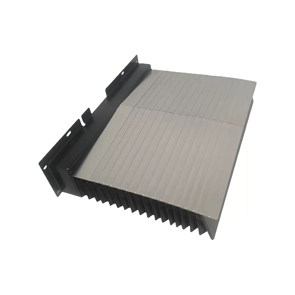
Modern industrial manufacturing demands high precision, rapid axis acceleration, and continuous operation. In CNC machining centers, boring mills, and automated gantry systems, the linear guide ways, ball screws, and feedback encoders are vital to operational accuracy. These components operate in extremely hostile environments filled with hot metal swarf, abrasive ceramic dust, and high-pressure chemical coolants. Without robust shielding, these foreign materials can cause immediate surface scoring, premature wear, and costly machine downtime.
To prevent such degradation, a durable physical barrier is required to isolate sensitive movement mechanisms from the machining zone. A custom-engineered telescopic steel cover serves as the primary line of defense. These structures must withstand continuous high-velocity cycles while maintaining a tight seal against ingress. QUNHUI designs and manufactures heavy-duty way protection systems engineered to meet these rigorous operational demands.
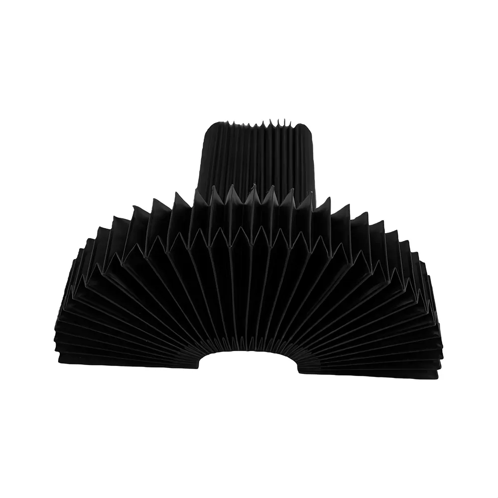
Structural Anatomy of Industrial Way Covers
A telescopic steel cover is a complex mechanical assembly composed of multiple nested sheet metal sections that slide relative to one another. Understanding the function of each individual component is necessary for selecting the appropriate protective configuration.
Steel Box Sections
The individual boxes, or plates, form the structural shell of the cover. These sections are typically fabricated from high-tensile cold-rolled steel or stainless steel sheets, with thicknesses ranging from 1.5 mm to 3.0 mm depending on the size of the machine tool. Stainless steel is often selected for environments characterized by corrosive coolants or high moisture levels, as it resists oxidation and pitting. The geometry of these boxes must be precise; even minor deviations in flatness or parallel alignment can cause binding during high-speed travel.
Wiper Systems
Mounted on the leading edge of each overlapping box, the wiper system performs a dual role. It cleans the surface of the adjacent inner section during compression and prevents coolants and micro-fine chips from entering the interior space. Wipers consist of a synthetic rubber profile, such as polyurethane, nitrile butadiene rubber (NBR), or Fluorocarbon elastomer (FKM/Viton), vulcanized or mechanically clamped to a steel support strip. Some harsh environments involving sharp, hot brass or steel shavings require the integration of a brass or stainless steel pre-wiper to deflect larger debris before the synthetic lip makes contact.
Guide Shoes and Support Rollers
To ensure smooth sliding motion along the machine bed guide rails, the individual steel sections rely on support elements. Guide shoes, machined from low-friction materials like brass, bronze, or engineered polymers (such as UHMWPE or PTFE), are attached to the underside of the boxes. For larger, heavier cover assemblies, needle-bearing support rollers are integrated to carry the dead weight of the steel plates, reducing the sliding friction coefficient and preventing stick-slip phenomena at slow feed rates.
Damping and Linkage Mechanisms
At high travel speeds, the rapid extension of the cover sections can generate substantial impact forces as each segment reaches its maximum stroke. Damping devices, such as polyurethane bumpers or spring cushions, are placed at contact points to absorb these kinetic shocks. In high-velocity machining centers, scissor-style pantograph linkages are installed on the underside of the cover. These link systems distribute the total stroke length evenly across all sections simultaneously, avoiding sudden impacts and minimizing noise.
Dynamic Forces and High-Velocity Challenges
The rapid evolution of linear motor drives has pushed CNC axis velocities beyond 60 meters per minute, with accelerations exceeding 1 to 2 Gs. These operational speeds subject the telescopic steel cover to immense mechanical stress. When the machine axis reverses direction rapidly, the inertial forces acting on the steel plates can lead to structural distortion if the cover is not properly balanced.
Unbalanced forces often lead to a phenomenon known as yawing, where one side of a steel box retracts faster than the other. This twisting action causes the guide shoes to bind against the guide rails, leading to rapid wear of the wipers and potential deformation of the steel sheet. To counter these forces, high-speed covers must be designed with minimal weight without compromising structural rigidity. Utilizing high-strength, thin-gauge alloys paired with precision-engineered pantographs ensures the assembly moves in perfect synchronization with the machine axis.
Another dynamic concern is the management of coolant pressure. Modern machine tools utilize high-pressure coolant (HPC) systems delivering fluids at pressures up to 70 bar directly to the cutting zone. This intense fluid spray can find its way through microscopic gaps in the wiper seals. Consequently, the wiper profile geometry must feature specific pre-tensioned sealing lips designed to deflect high-velocity liquid streams away from the seam lines.
Application Profiles Across Diverse Industrial Machinery
Different machine tool layouts present unique environmental challenges, requiring distinct design variations for the protective shielding.
Horizontal Machining Centers (HMC): The axes on horizontal machines are subjected to continuous cascades of heavy chips dropping directly onto the horizontal surfaces of the cover. For these setups, a sloped or "roof-shaped" telescopic steel cover profile is utilized. The angled surfaces allow chips and coolant to slide off naturally via gravity, preventing accumulation that could obstruct retraction.
Vertical Machining Centers (VMC): Vertical axes require covers that operate in a vertical orientation. In this configuration, gravity assists the expansion of the upper sections but resists their compression during upward travel. The cover must be designed with robust counter-balances or guide mechanisms to prevent sagging, ensuring that the heavy steel boxes remain parallel to the column face during vertical travel.
Large Gantry Boring Mills: These massive machines feature wide spans and long travel distances, sometimes exceeding 10 meters. The sheer weight of the steel boxes in these applications requires heavy-duty guide tracks and high-capacity roller bearings. The covers are often designed with walk-on capabilities, featuring reinforced internal support frames and anti-slip tread plates so operators can safely walk across them during setup procedures.
Specifying Custom Way Protection
Developing an effective telescopic steel cover requires careful calculations and a thorough understanding of the specific operating parameters of the machine. Engineering a replacement or a new system involves analyzing several dimensional variables.
The ratio between the maximum extended length (L-max) and the minimum compressed length (L-min) is a key limiting factor in cover design. Each additional steel box section increases the compressed length because of the thickness of the metal sheet, the wiper holder, and the internal clearance guides. If the available space on the machine bed is limited, engineers must maximize the number of sections while minimizing the depth of each segment to achieve the required stroke length.
The mechanical parameters that must be evaluated include:
Maximum Stroke: The actual travel distance of the machine tool slide.
Mounting Interface: The physical dimensions of the bracket plates connecting the cover to both the moving slide and the stationary machine bed.
Maximum Speed and Acceleration: These metrics dictate whether a simple drag-style cover is sufficient or if a complex pantograph link system is necessary to distribute kinetic energy.
Wiper Material Compatibility: The chemical formulation of the machine's coolant (water-soluble, synthetic, or neat oil) must be cross-referenced with the elastomer properties of the wiper to prevent swelling or embrittlement.
QUNHUI utilizes advanced design software to simulate these kinematic forces, ensuring that the custom telescopic steel cover maintains its structural integrity throughout millions of operational cycles.
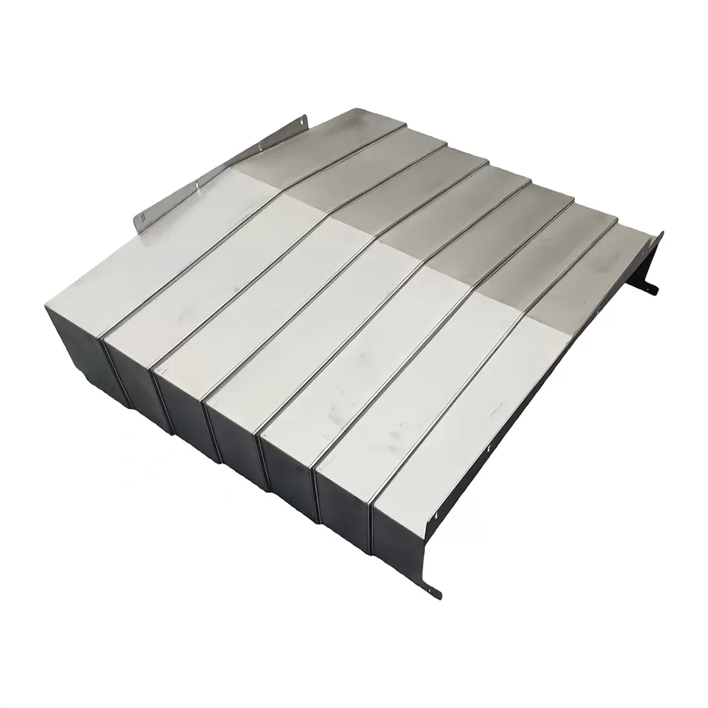
Preventative Maintenance and Reconditioning
Despite their robust construction, telescopic covers are wear items that require scheduled maintenance to achieve their maximum service life. Implementing a structured maintenance routine helps prevent catastrophic failures that can halt production lines.
Daily cleaning is the first line of defense. Operators should clear away large nests of stringy chips and heavy accumulations of abrasive sludge from the top surfaces of the covers before starting a shift. When left on the cover, these abrasive particles can be pulled under the wiper lips during compression, scratching the highly polished metal surfaces and destroying the wiper profile.
Monthly inspections should focus on the condition of the wiper lips. Any signs of tearing, hardening, or chemical degradation indicate that a wiper replacement is necessary. Additionally, the guide shoes and brass sliders should be checked for wear. If the brass shoes wear down completely, the steel-on-steel contact between the cover and the machine guide rails will cause severe scoring of the machine’s precision surfaces.
Periodically, the entire cover assembly should be removed from the machine for deep cleaning, alignment verification, and replacement of all wear components. Reconditioning a slightly deformed cover early is far more cost-effective than replacing a completely crushed cover following an unexpected axis collision.
Frequently Asked Questions
Q1: What materials are typically used to manufacture a telescopic steel cover?
A1: High-strength cold-rolled carbon steel is standard for general machining applications due to its excellent structural rigidity and impact resistance. For environments involving corrosive coolants, acidic compounds, or high humidity, stainless steel is utilized to prevent oxidation and ensure smooth, rust-free telescoping action.
Q2: How do I know when the wiper blades on my telescopic cover need replacement?
A2: Wipers should be inspected if you notice coolant leaking into the interior of the cover, fine chips accumulating on the guide rails behind the cover, or visual signs of cracking, swelling, or tearing along the polyurethane lip. In typical multi-shift production environments, replacing wipers every 12 to 18 months is recommended.
Q3: Can a bent or dented telescopic steel cover section be repaired?
A3: Yes, minor dents and structural warpage can often be repaired by experienced technicians who specialize in sheet metal flattening and alignment. However, if the structural boxes are severely crushed or twisted from a high-speed tool collision, replacing the damaged sections or the entire assembly is necessary to prevent damage to the machine's linear rails.
Q4: What is the primary purpose of a pantograph system on a telescopic cover?
A4: A pantograph, or scissor linkage, coordinates the movement of all the sliding sections so they expand and retract at the same relative speed. This avoids the abrupt physical impacts that occur when one section pulls the next, reducing mechanical noise, vibration, and localized stress during high-speed travel.
Q5: How do synthetic coolants affect the choice of wiper materials?
A5: Synthetic and semi-synthetic coolants contain chemical additives that can cause standard polyurethane or nitrile rubbers to degrade, swell, or lose their elasticity over time. When these coolants are used, specialized elastomers such as Viton (FKM) or chemically resistant polyurethane formulations are specified to ensure the seals remain functional.
Q6: Is it possible to retrofit an existing CNC machine with a walk-on telescopic steel cover?
A6: Yes, retrofitting is possible. It requires reinforcing the internal structural ribs of the steel sections and incorporating heavier guide supports or rollers to handle the load of a human operator. The machine bed must also have sufficient space to accommodate the larger physical envelope of a reinforced walk-on cover design.
Contact QUNHUI for Engineered Solutions
Protecting your machine tool assets requires high-quality shielding systems tailored to your specific application challenges. QUNHUI engineers custom-built protective way cover systems designed to meet your precise space constraints, velocity parameters, and environmental exposures. Our technical team works closely with you to design, manufacture, and deliver durable solutions that minimize maintenance costs and extend the operational life of your CNC machinery. To request a technical consultation, submit your dimensional drawings, or receive a detailed quotation for a custom telescopic steel cover system, please contact our sales department today.